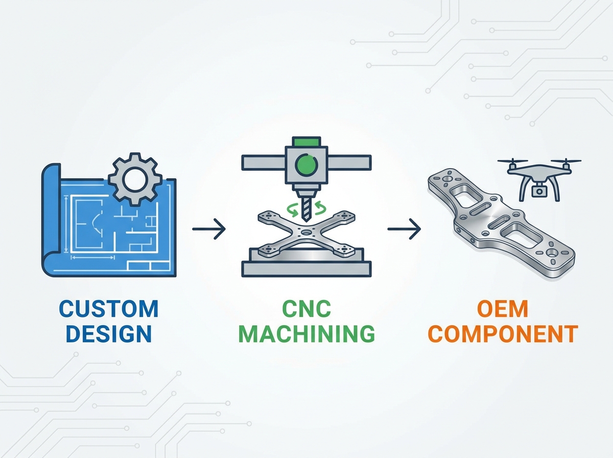
The transition from hobbyist UAV builds to commercial, defense, or industrial drone manufacturing requires a fundamental shift in production methodology, where rapid prototyping methods fall short of required structural integrity. Commercial UAV OEMs must balance extreme weight reduction with the mechanical rigidity required for heavy payloads, high-speed maneuvers, and vibration-sensitive optics, all while scaling production predictably. Securing a reliable manufacturing partner for cnc machining for drone components is critical. This guide breaks down the technical criteria, material trade-offs, and quality assurance frameworks necessary to evaluate and select an OEM machining partner. We look directly at the spindle-level realities of manufacturing airframes that survive harsh field conditions.
Material dictates mission capability: Selecting between aerospace-grade aluminum, carbon fiber, and titanium fundamentally alters the payload-to-weight ratio and manufacturing costs.
Precision equals data integrity: Ultra precision CNC parts are non-negotiable for motor mounts and gimbal housings, where micro-vibrations can degrade sensor and camera data.
Scalability requires process control: Moving from prototype to full-scale production demands an OEM partner with strict AS9100/ISO 9001 compliance, automated 5-axis capabilities, and verifiable CMM inspection processes.
Finishing is functional, not just aesthetic: Surface treatments like hard-coat anodizing are critical for environmental resistance and EMI shielding in commercial drone applications.
Commercial drones require components that exhibit high tensile strength, minimal weight, and exact repeatability across thousands of units. When you hang a heavy multispectral camera or a LiDAR unit off a multirotor, frame flex destroys your data. Engineers need chassis elements that handle aggressive flight envelopes without yielding. You cannot achieve this with hobby-grade plastics or layered extrusions. The airframe must act as a rigid, unified structure.
Comparing CNC machining against 3D printing (FDM/SLA) and injection molding shows a clear divide in structural performance. 3D printing leaves you with anisotropic parts. They snap along layer lines under shear stress. Injection molding gives you better isotropic properties but traps you behind massive upfront tooling investments. If you need to change a mounting hole location, you have to modify a steel mold. CNC machining cuts solid billet material. You get the maximum load-bearing capacity of the raw alloy without the tooling delays. You can update a toolpath in CAM software in minutes.
Moving from iterative design to locked-in oem drone machining forces a strict adherence to Design for Manufacturability (DFM). You have to design parts that a machine can actually cut efficiently. This means eliminating deep, narrow pockets that require fragile, extended-reach endmills. It means standardizing internal corner radii so the machinist does not have to swap tools five times for one pocket. Good DFM reduces cycle times, drops material waste, and keeps the spindle running.
We see many engineering teams struggle because they design parts for the screen, not the machine. A beautifully rendered chassis plate might require custom workholding and six different setups to manufacture. By flattening the design and utilizing standard stock sizes, you cut production time in half. The goal is to get the part off the machine in as few operations as possible.
Motor mounts and arm joints take the worst abuse during flight. They handle the direct torque of the motors and the harmonic vibrations of the propellers. Rigid, heat-dissipating aluminum drone parts are mandatory here. Aluminum acts as a heat sink, pulling thermal loads away from the motor stators. If you machine these mounts with poor concentricity, you introduce harmonic resonance. That resonance travels down the carbon fiber arms and shakes the flight controller, leading to erratic flight behavior.
The core chassis and structural plates serve as the central hub where payload, battery, and avionics converge. Machining these plates requires aggressive lightweighting. We use high-speed machining (HSM) toolpaths to pocket out excess material while leaving structural ribs intact. You want a web-like structure that resists torsion but weighs almost nothing. Workholding is difficult here. Thin plates want to warp when you machine away the skin of the billet. Machinists use vacuum chucks or double-sided tape fixtures to hold the material flat during heavy roughing passes.
Gimbal housings and sensor enclosures protect the most expensive parts of the drone. You need ultra precision cnc parts to ensure perfect optical alignment. A misalignment of a few thousandths of an inch in a gimbal arm translates to massive image distortion at a distance of 400 feet. We machine these enclosures to exact focal distances, ensuring the lenses sit perfectly square to the sensors.
Do not ignore the small hardware. Payload release mechanisms, antenna mounts, landing gear brackets, and custom turned standoffs hold the entire system together. These cnc drone accessories maintain structural rigidity between the upper and lower frame plates. If you use cheap, extruded standoffs, the frame will twist under load. Custom turned titanium or aluminum spacers with precise tapped holes ensure the chassis remains a rigid box.
Your material choice dictates the operational limits of the aircraft. You have to balance yield strength, weight, and machinability. Every alloy behaves differently when the endmill hits it.
Aluminum alloys are the backbone of the industry. 6061-T6 is the workhorse. It machines beautifully, chips break easily, and it resists corrosion. We use it for standard structural plates and electronic enclosures. 7075-T6 is a different beast. It is alloyed with zinc and offers aerospace-grade strength comparable to some steels, but at a fraction of the weight. It is harder on cutting tools but is the absolute standard for high-stress motor mounts and folding arm clamps.
Machining drone frame components out of quasi-isotropic carbon fiber plates requires specific setups. Carbon fiber is highly abrasive. Standard carbide endmills dull in minutes. You must use Polycrystalline Diamond (PCD) coated tooling to cut it cleanly. If the tool gets dull, it pushes the material instead of cutting it, causing delamination and fiber breakout. You also have to manage the dust. Carbon dust is conductive and will destroy machine electronics. We use specialized high-velocity dust collection systems or wet cutting techniques to keep the dust out of the spindle bearings.
Titanium and magnesium fit niche, extreme-environment applications. Titanium (Ti-6Al-4V) offers incredible strength and heat resistance. However, it has terrible thermal conductivity. The heat from the cut goes into the tool, not the chip. You have to run low surface speeds and high feed rates to prevent work hardening. Magnesium is incredibly light, but the chips are highly flammable. Machining magnesium requires strict fire suppression protocols and specific coolant strategies to prevent shop fires.
Material | Primary Benefit | Machinability | Ideal Drone Application |
|---|---|---|---|
Aluminum 6061-T6 | Corrosion resistance, lightweight | Excellent | Standard chassis plates, spacers |
Aluminum 7075-T6 | High tensile strength | Good | Motor mounts, folding arm joints |
Carbon Fiber | Maximum stiffness-to-weight ratio | Poor (Requires PCD tooling) | Main frame arms, structural decks |
Titanium (Ti-6Al-4V) | Extreme strength, heat resistance | Difficult | High-stress fasteners, landing gear |
Standard commercial tolerances do not work in the air. You need aerospace-grade precision. Bearing bores in motor mounts require tight tolerances, usually between ±0.005mm and ±0.01mm. If the bore is too large, the bearing slips and spins in the housing, destroying the mount. If it is too tight, you crush the bearing races, causing premature motor failure. We use boring heads and precision reamers to hit these numbers consistently.
Complex drone assemblies require a mix of CNC milling and turning. Milling handles the flat frame plates, gimbal arms, and prismatic bodies. CNC turning centers handle the round parts. We turn ultra-precise arm connectors, knurled spacers, and custom motor shafts on lathes. Integrating both processes ensures that when you bolt a turned arm tube into a milled clamping block, the mating surfaces align perfectly without inducing stress into the frame.
Automated 5-axis CNC milling changes the game for complex geometries. A 5-axis machine can reach five sides of a part in a single setup. This eliminates the need to unclamp the part, flip it, and indicate it back in. Every time you move a part, you lose accuracy. Single-setup machining drastically improves concentricity across multiple features. It allows us to machine aerodynamic, sweeping curves on gimbal housings without leaving step-over marks.
Vibration mitigation starts at the machine spindle. Exact runout control is critical. If a motor mount is machined asymmetrically, it creates a mass imbalance. When that motor spins at 10,000 RPM, that imbalance creates a high-frequency vibration. We use balanced toolholders and precision collets to ensure the machined features are perfectly symmetrical around the center axis.
Raw aluminum oxidizes and scratches easily. You have to protect it. Hard-coat anodizing (Type III) builds a thick layer of aluminum oxide on the surface. This improves wear resistance significantly. It also provides excellent dielectric properties. If a frayed wire touches a Type III anodized frame, it will not short out the system. Type II anodizing is thinner but allows for color dyeing, which helps with visual orientation during flight.
Drones operating near power lines, cell towers, or in defense environments face massive electromagnetic interference. Electroless nickel plating and chromate conversion coatings provide EMI/RFI shielding. These finishes create a conductive layer that blocks external radio frequencies from penetrating the avionics enclosures. You must mask off threaded holes before plating to ensure fasteners still fit.
Deburring is a functional requirement, not just a cosmetic one. Sharp edges act as stress risers. Under heavy flight loads, a micro-crack will form at a sharp corner and propagate through the part until it fails. Sharp edges also chafe wiring harnesses. We use automated vibratory tumbling or precision manual deburring under magnification to break all sharp edges and ensure the wiring remains intact.
The quoting phase bogs down when engineers submit poor files. You need to standardize your CAD submissions. Send STEP or IGES files for all 3D milled or turned components. Send DXF or DWG files for flat-cut carbon fiber plates. Most importantly, include a 2D PDF drawing. The 3D model tells the machine what shape to cut, but the 2D drawing tells the machinist which tolerances actually matter. Call out your threaded holes clearly.
Many commercial platforms start from open-source reference designs like PX4 or ArduPilot. A capable machine shop routinely handles custom drone cnc modifications based on these files. We take the community-driven geometries and optimize them for high-volume manufacturing. We adjust wall thicknesses to prevent chatter during machining and standardize mounting patterns to reduce tool changes.
Top-tier machining partners use automated DFM feedback to minimize lead times. When you submit a file, we run it through CAM simulation to identify unmachinable features instantly. We flag deep pockets, sharp internal corners, and impossible tolerances before the first chip is cut. This rapid feedback loop allows us to target a 5-to-10 day window for pilot runs.
You cannot compromise on quality assurance. Demand AS9100 or ISO 9001:2015 certifications from your machining partner. Verify their inspection equipment. They need a Coordinate Measuring Machine (CMM) to verify complex 3D geometries. Require First Article Inspection (FAI) reports for the initial batch. This proves the shop can actually hit the tolerances called out on your drawings.
Cost structures change as you scale. In low-volume prototyping, programming time and machine setup fees dominate the invoice. When you move to high-volume production, cycle times and material yield dictate the unit cost. A reliable partner optimizes toolpaths, builds custom multi-part fixtures, and orders material in bulk to drive down the per-unit expense as volume increases.
Evaluate how the shop handles volume scaling. A shop that makes beautiful prototypes might fail completely when asked for 10,000 units. Look at their spindle count. Look at their automation. Do they have robotic part loaders or pallet pools? You need a partner with the machine capacity and supply chain stability to handle large production runs without missing delivery dates.
Material traceability is non-negotiable. You must demand mill test certificates (MTCs) for every batch of material. Counterfeit aluminum is a real problem in global supply chains. If you machine a motor mount out of fake 7075-T6, it will fail in mid-air. MTCs prove the chemical composition and yield strength of the raw billet before it enters the machine.
Protect your intellectual property. Drone designs are highly proprietary. Demand strict Non-Disclosure Agreements (NDAs) before sending any files. Ensure the manufacturer uses secure, encrypted portals for CAD file handling and maintains segmented internal networks to prevent data breaches.
Custom CNC machining provides the structural integrity and precision required for mission-critical drone components. Additive manufacturing cannot match the load-bearing capacity of machined billet alloys. To ensure your production line runs smoothly, you must partner with a shop that understands aerospace tolerances, utilizes 5-axis technology, and enforces strict quality control.
Finalize your CAD models and ensure all critical tolerances and threaded holes are explicitly defined on accompanying 2D PDF drawings.
Submit your design files to a certified machining partner for a comprehensive Design for Manufacturability (DFM) review to eliminate unmachinable features.
Request a low-volume pilot run to physically validate component fitment, weight, and structural integrity before committing to mass production.
Establish a clear quality control agreement that mandates CMM inspection reports and mill test certificates for all raw materials.
A: Aluminum 7075-T6 is the best choice for high-stress components like motor mounts and folding arm joints due to its exceptional strength-to-weight ratio. For less critical structural plates where corrosion resistance and machinability are the priorities, 6061-T6 is the standard alternative.
A: At production scale, unit costs drop significantly because programming and setup times are amortized across thousands of parts. Cycle time, raw material yield, and the use of automated multi-part fixturing become the primary cost drivers. Optimizing designs for faster machining reduces high-volume production expenses.
A: Yes, but it requires specialized techniques. Machinists must use Polycrystalline Diamond (PCD) router bits and highly optimized feed rates. Proper vacuum fixturing and compression tooling prevent the composite layers from separating or splintering during the high-speed cutting process.
A: Standard structural components typically hold ±0.05mm. However, critical interfaces like bearing bores, motor shaft alignments, and gimbal optical mounts require tight tolerances ranging from ±0.005mm to ±0.01mm to prevent vibration and ensure sensor data integrity.
A: For 3D milled or turned aluminum parts, STEP or IGES files are the industry standard. For 2D flat-cut carbon fiber plates, DXF or DWG files are preferred. Always include a 2D PDF drawing calling out specific tolerances and threaded hole requirements.
A: A capable manufacturing partner can transition a validated prototype into full production within 2 to 4 weeks. This timeline depends on raw material availability, the complexity of custom fixturing required for mass production, and the finalization of quality inspection protocols.
A: 5-axis milling allows complex, multi-sided geometries to be machined in a single setup. This reduces manual handling, eliminates alignment errors between setups, and ensures perfect concentricity for aerodynamic components and specialized payload mounts.