Aerospace structural engineering demands materials that deliver high strength-to-weight ratios, extreme environmental resistance, and absolute dimensional reliability. Flight components face severe mechanical stress and harsh atmospheric conditions, requiring manufacturing processes that guarantee long-term durability. Engineers must achieve complex geometries without compromising the structural integrity of the final part. The practical solution involves combining advanced anodized aluminum cnc milling with high-grade alloys to produce flight-ready, mission-critical components.
This engineering guide outlines the technical decision-making criteria for aerospace design engineers, procurement professionals, and quality assurance managers. We examine material selection, advanced manufacturing techniques, dimensional precision, and the stringent quality standards required to produce reliable aerospace structures. You will find actionable data on alloy properties, machining strategies, and surface treatment calculations to optimize your next aerospace project.
Selecting the right aluminum alloy forms the foundation of reliable aerospace manufacturing. Different alloys offer varying balances of yield strength, fatigue resistance, and corrosion protection. Understanding these metallurgical properties helps engineers specify the correct material for specific structural applications on the aircraft.
Aluminum 7075-T6 offers the highest strength-to-weight ratio and excellent fatigue resistance among standard aerospace materials. Engineers specify this alloy for highly stressed aerospace structural components such as wing spars, fuselage frames, and load-bearing bulkheads. Aluminum 6061-T6 provides superior corrosion resistance and remains highly weldable. Shop floors frequently machine it for internal brackets, electronic enclosures, and custom assembly fixtures. Aluminum 2024-T3 delivers high damage tolerance and fatigue crack growth resistance. This makes it the standard choice for fuselage skins and tension members subjected to continuous cyclic loading during flight.
| Aluminum Alloy | Yield Strength (MPa) | Primary Alloying Element | Typical Aerospace Application | Anodizing Compatibility |
|---|---|---|---|---|
| 7075-T6 | 503 | Zinc | Wing spars, bulkheads | Fair (Requires specific process control) |
| 6061-T6 | 276 | Magnesium/Silicon | Brackets, enclosures | Excellent |
| 2024-T3 | 345 | Copper | Fuselage skins | Poor to Fair (Prone to pitting) |
The alloying elements within aluminum significantly affect the anodizing process and the final coating quality. High copper content in 2xxx series alloys complicates the electrochemical reaction. This often results in a less uniform coating, lower dielectric strength, or reduced corrosion protection compared to other series. Zinc in 7xxx series alloys influences anodizing density and color consistency, sometimes producing a yellowish or gray tint in clear anodize. Engineers must account for these chemical interactions when specifying surface treatments. Proper alloy selection ensures the final component meets functional requirements without compromising the protective oxide layer.
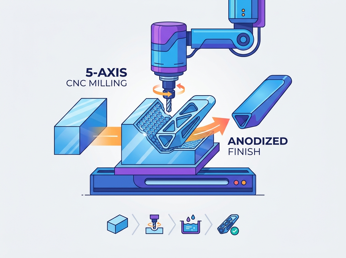
Modern aerospace designs feature intricate, organic shapes that require advanced manufacturing techniques. Utilizing 5 axis cnc machining allows shops to produce these complex geometries efficiently while holding tight tolerances across multiple planes.
Traditional 3-axis machining requires multiple setups to complete a complex part. Each setup introduces the potential for alignment errors and tolerance stacking. 5-axis machining eliminates these multiple setups by allowing the cutting tool to approach the workpiece from nearly any angle. This capability allows manufacturers to maintain strict geometric dimensioning and tolerancing (GD&T) across the entire part. It proves especially valuable for machining the complex organic shapes, deep cavities, and thin-walled structures typical of modern aircraft components.
Machining aerospace components presents unique challenges on the shop floor, particularly when dealing with thin-walled structures. Machinists must deploy specific strategies to prevent chatter, vibration, and thermal warping in sections under 1mm thick.
Achieving dimensional precision requires a deep understanding of how surface treatments affect the final part geometry. Engineers must calculate the exact impact of anodizing buildup to ensure components assemble correctly on the production line.
Anodizing is an electrochemical process that converts the metal surface into a durable, corrosion-resistant anodic oxide finish. The coating mechanism typically involves 50% penetration into the substrate and 50% buildup on the surface. If a specification calls for a coating that is 0.002 inches thick, the part's physical dimension will increase by 0.001 inches per surface. This means a bore diameter will shrink by 0.002 inches total, while an outer shaft diameter will grow by 0.002 inches.
Type II anodizing provides a decorative and corrosion-resistant finish. It produces a typical buildup of 0.0002 to 0.001 inches (5 to 25 microns). Type III hardcoat anodizing delivers a wear-resistant and highly insulating surface. It generates a typical buildup of 0.001 to 0.003 inches (25 to 75 microns). Hardcoat anodizing serves high-friction applications where durability and abrasion resistance are mandatory.
| Anodizing Type | Typical Thickness | Surface Buildup | Primary Characteristics |
|---|---|---|---|
| Type II (Sulfuric) | 0.0002" - 0.001" | 50% of total thickness | Corrosion resistance, color dyeing |
| Type III (Hardcoat) | 0.001" - 0.003" | 50% of total thickness | Extreme wear resistance, electrical insulation |
Engineers must design parts with pre-anodize dimensions that explicitly account for the expected coating buildup. This involves calculating offsets for threaded holes, press-fit bearings, and precise mating surfaces. You must specify masking requirements on the engineering drawing for electrical grounding points and critical-tolerance mating faces. By carefully managing these variables, manufacturers achieve ultra-precise tolerances down to ±0.0002 inches on finished precision cnc parts.
Surface preparation directly impacts the quality, adhesion, and performance of the anodized finish. Proper techniques ensure the coating forms uniformly and provides the required environmental protection.
Media blasting, specifically bead blasting, helps achieve uniform matte finishes and hides minor tool marks left from the milling process. Chemical etching prepares raw milled surfaces by removing microscopic impurities and smoothing the surface at a chemical level. Maintaining surface roughness standards of Ra 32 or better prior to anodization prevents microscopic structural stress-raisers. Rough surfaces can cause the anodic coating to form unevenly, potentially leading to premature fatigue failure in high-stress aerospace applications.
After anodizing, quality control teams conduct rigorous inspections to verify the coating's integrity. Coating thickness verification using eddy-current testing ensures the buildup meets specified tolerances across the entire part geometry. Salt spray corrosion testing confirms compliance with military and aerospace standards, specifically MIL-A-8625 or MIL-PRF-8625. These tests guarantee the part will perform reliably in harsh, corrosive flight environments.
Anodized aluminum components operate throughout the aircraft, serving both structural and functional roles. Their unique combination of light weight, high strength, and surface durability makes them indispensable for modern aviation.
Wing spars and ribs represent high-stress load paths requiring extreme fatigue life and robust corrosion protection. Bulkheads and frames form the skeleton of the fuselage. Shops often machine these complex, lightweight structures from single aluminum billets to eliminate joint failures, reduce fastener counts, and lower overall aircraft weight.
Electronic systems require robust protection from environmental factors and electromagnetic interference. Engineers design anodized aluminum parts specifically for thermal management, EMI shielding, and environmental sealing. These enclosures ensure sensitive avionics, navigation systems, and payload sensors operate reliably under varying atmospheric pressures and temperatures.
Actuation systems and landing gear operate under severe mechanical stress and exposure to runway debris. Wear-resistant, hard-anodized sleeves, hydraulic manifolds, and mounting brackets provide the necessary durability. The Type III hardcoat finish withstands repeated mechanical cycles and harsh environmental exposure without degrading.
Manufacturing aerospace components requires strict adherence to quality management systems and regulatory standards. Compliance ensures every machined part meets the rigorous safety and performance requirements of the aviation industry.
Navigating the strict regulatory framework required for cnc aerospace parts manufacturing involves maintaining active certifications like AS9100 Rev D and ISO 9001. These standards dictate comprehensive quality management processes. They cover everything from initial contract review and risk management to final inspection and non-conformance tracking.
Complete material pedigree is non-negotiable in aerospace manufacturing. Suppliers must provide Mill Test Reports (MTRs) and Certificate of Conformance (CoC) validation with every batch of raw material. This documentation ensures the aluminum billets meet exact chemical and mechanical specifications before any machining begins.
Advanced inspection protocols verify dimensional accuracy and structural integrity before parts ship. Coordinate Measuring Machine (CMM) scanning verifies complex aerodynamic profiles and tight tolerances against the original CAD models. Non-Destructive Testing (NDT), including liquid penetrant inspection, detects micro-cracks post-milling and post-anodizing. This ensures the part remains free of critical defects that could propagate during flight.
Choosing a manufacturing partner involves evaluating their technical capabilities, quality systems, and production capacity. A reliable machine shop contributes significantly to the success and safety of an aerospace project.
A competent manufacturer provides early-stage Design for Manufacturability (DFM) feedback. This includes practical guidance on corner radii, deep pocket milling strategies, and anodizing limitations. Early DFM helps engineers optimize designs for efficient production, reducing machining time and lowering scrap rates.
Sourcing from partners who manage both the raw milling and specialized anodization under a single quality management system offers distinct advantages. Vertical integration reduces logistical complexities and eliminates finger-pointing between the machine shop and the finishing house. It shortens lead times and ensures consistent quality control throughout the entire manufacturing process.
A capable partner must accommodate varying production needs. They should handle everything from rapid aerospace prototyping to long-term production contracts and blanket orders. Evaluating their machine capacity and scalability ensures they can meet strict delivery schedules as project demands evolve.
To ensure successful procurement of aerospace structural components, execute these next steps:
A: Aluminum 7075-T6 offers the highest strength-to-weight ratio among common aluminum alloys. It provides excellent fatigue resistance, making it ideal for highly stressed structural components like wing spars, frames, and load-bearing bulkheads.
A: 5-axis machining allows the cutting tool to approach the part from multiple angles without requiring manual repositioning. This eliminates multiple setups, reduces alignment errors, and maintains strict geometric dimensioning and tolerancing across complex parts.
A: Type II anodizing provides a decorative, corrosion-resistant finish with minimal thickness buildup. Type III hardcoat anodizing creates a thicker, highly wear-resistant, and electrically insulating surface designed specifically for high-friction and heavy-wear applications.
A: Surface preparation, such as bead blasting or chemical etching, removes impurities and tool marks. This ensures uniform coating adhesion and prevents microscopic structural stress-raisers that could compromise the part under heavy mechanical loads.
A: Engineers calculate the expected anodizing buildup and design pre-anodize dimensions with specific offsets. Manufacturers also use precise masking techniques on critical mating surfaces and threaded holes to maintain tight tolerances after the coating process.
A: AS9100 is a stringent quality management standard specific to the aerospace industry. It ensures manufacturers maintain rigorous, documented processes for risk management, material traceability, inspection, and overall production quality control.