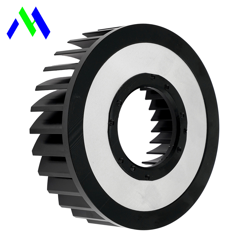
High-wattage LED applications rapidly exceed the thermal dissipation capabilities of traditional passive and active air cooling. Systems used in UV curing, horticultural lighting, stadium arrays, and industrial inspection generate massive thermal loads. When these arrays operate, excessive junction temperatures ($T_j$) become a primary failure mode. High heat density leads to accelerated lumen depreciation, spectral shifts, and premature catastrophic failure. These thermal issues directly impact operational reliability and warranty liabilities. When spatial constraints and thermal density render standard forced-air solutions obsolete, engineering a liquid cooling loop becomes the necessary path. Liquid cooling maintains performance, ensures longevity, and optimizes volumetric efficiency. Transitioning to liquid cold plates allows engineers to manage extreme heat fluxes while keeping the physical footprint minimal. We will evaluate thermal limits, select appropriate cold plate topologies, and implement robust liquid cooling loops for high-power lighting arrays.
Thermal Limits: Liquid cooling systems offer a thermal conductivity up to 24 times higher than air, making them mandatory for LED arrays exceeding specific heat flux thresholds (typically >50W/cm²).
Material & Topology: The choice between a standard aluminum heat sink and a copper-based liquid cold plate dictates both thermal resistance and long-term corrosion management.
System Complexity vs. Yield: While a water cooled heat sink introduces mechanical complexity (pumps, plumbing), it allows for significantly higher lumen output in constrained form factors, altering the long-term operational equation.
Risk Mitigation: Successful deployment requires strict adherence to galvanic corrosion prevention, leak-proof sealing standards, and condensation management.
Natural convection and forced-air systems possess inherent thermal resistance bottlenecks. Air has a low specific heat capacity and poor thermal conductivity. As LED power density increases, standard cooling methods fail to remove heat fast enough. The boundary layer of air clinging to the fin surfaces acts as an insulator. Pushing more air over the fins requires high-RPM fans, which introduce severe acoustic noise and mechanical failure points. In harsh industrial environments, fans pull in dust, vapor, and debris, which quickly clog the fin channels and degrade thermal performance over time.
Volumetric constraints quickly become apparent in high-power designs. There is a strict limit to how much you can increase the fin density or surface area of a traditional aluminum heat sink. Standard star-profile extrusions eventually yield diminishing returns. Tightly packed fins cause flow bypass, where air travels around the heat sink rather than through it. Boundary layer interference between closely spaced fins chokes the airflow, rendering the extra surface area useless. Engineers often find that doubling the size of the extrusion yields only a marginal drop in thermal resistance, making passive cooling unviable for dense arrays.
Acoustic and mechanical limitations further restrict forced-air solutions. In sensitive environments like film studios, medical operating rooms, or broadcast arenas, the decibel output of high-speed cooling fans is unacceptable. Furthermore, the vibration generated by fan motors can cause micro-abrasions on the LED substrate or loosen mounting hardware over thousands of operating hours. Moving away from moving air to a pumped liquid system eliminates these localized mechanical and acoustic issues.
Junction temperature directly dictates LED lifespan. The IES LM-80 and TM-21 degradation curves show a sharp drop in L70 life as $T_j$ rises. Operating an LED array just 10 degrees above its optimal junction temperature can halve its operational lifespan. Thermal throttling becomes necessary if the cooling system cannot handle the load. Throttling reduces the drive current to save the diodes, but it ruins luminous efficacy and causes color rendering index (CRI) shifts. You cannot rely on throttling in systems that demand continuous, peak-output performance.
Precision lighting applications cannot tolerate these spectral shifts. UV curing requires exact wavelength peaks to polymerize resins. Horticultural lighting demands specific photon fluxes for plant growth. When heat flux exceeds 50W/cm², air cooling simply cannot maintain a stable $T_j$. This baseline heat flux parameter signals the absolute necessity to transition from air to liquid cooling. Maintaining a strict thermal envelope ensures the diodes emit the exact spectrum they were binned for at the factory.
We measure the success of a thermal management system by its ability to keep the junction temperature well below the manufacturer's absolute maximum rating. For high-density chip-on-board (COB) LEDs, the thermal path from the junction to the case ($R_{th, j-c}$) is fixed by the LED packaging. The only variable engineers can control is the case-to-ambient resistance ($R_{th, c-a}$). Liquid cooling drastically lowers this variable, providing the thermal headroom needed to push drive currents higher without destroying the semiconductor.
Internal flow path design dictates the thermal performance of a water cooled heat sink. Engineers utilize several channel topologies based on the required thermal resistance and allowable pressure drop. Serpentine tubes pressed into aluminum plates offer a simple, leak-resistant macro-channel solution. Gun-drilled channels provide straight flow paths for moderate heat loads. For extreme heat fluxes, skived fin micro-channels maximize the wetted surface area directly beneath the LED hot spots. These micro-channels force the fluid into a turbulent state, which strips away the thermal boundary layer and drastically increases heat absorption.
Modern design methodologies push channel topologies further. Generative design and topology optimization algorithms create complex internal geometries. Biomimetic shapes, mimicking organic branching or fractal patterns, distribute coolant evenly across the cold plate. These advanced structures maximize heat-transfer surface area while minimizing pressure drop. Manufacturing these complex internal structures requires specific techniques. CNC machining and vacuum brazing handle intricate micro-channels, while additive manufacturing enables true three-dimensional fluid paths that were previously impossible to fabricate.
The trade-off between manufacturing complexity and thermal performance is a constant engineering challenge. Extruded cold plates with pressed-in copper tubes are highly reliable and easy to produce, but they leave small air gaps that increase thermal resistance. Vacuum-brazed cold plates offer superior thermal contact and allow for complex internal routing, but they require specialized furnace equipment and strict quality control to prevent internal flux contamination. You must select the topology that matches the specific heat flux of your LED array.
Material selection fundamentally alters thermal resistance and system weight. Copper boasts a thermal conductivity of approximately 401 W/m·K. Aluminum offers around 205 W/m·K. For extreme high-power lighting assemblies, copper cold plates pull heat away from the LED substrate much faster. However, copper is significantly heavier and more difficult to machine. The high density of copper means a solid cold plate can add substantial mass to a lighting fixture, which complicates mounting and rigging.
Weight considerations are critical for suspended fixtures, dynamic robotic-arm-mounted LED heads, and architectural tracks. A heavy copper block may exceed the payload limits of a robotic arm or require reinforced truss systems in a stadium. In these cases, a lightweight aluminum cold plate is preferred. You must match the cold plate material with the rest of the liquid loop. Mixing copper cold plates with aluminum radiators in the same loop invites galvanic corrosion, which will destroy the system from the inside out.
Material | Thermal Conductivity (W/m·K) | Weight / Density (g/cm³) | Corrosion Risk (Mixed Loop) | Machinability |
|---|---|---|---|---|
Copper (C11000) | ~386 - 401 | 8.89 - 8.96 | High if mixed with Aluminum | Moderate (Gummy) |
Aluminum (6061-T6) | ~167 - 205 | 2.70 | High if mixed with Copper | Excellent |
Stainless Steel (304) | ~14 - 16 | 8.00 | Low | Difficult |
When designing a water cooled heat sink for LED applications, you must also consider the surface finish. The mating surface between the LED substrate and the cold plate must be exceptionally flat. We typically specify a surface flatness of 0.001 inches per inch and a surface roughness (Ra) of 32 microinches or better. Any deviation from these tolerances creates microscopic air gaps that act as thermal insulators, negating the benefits of the liquid cooling loop.
High-wattage LED systems rely on robust power electronics. LED drivers, power supplies, and control circuitry generate substantial waste heat. Auxiliary components often contribute 10-15% of the total system thermal load. Ignoring the driver temperatures leads to premature power supply failure, even if the diodes remain perfectly cool. Electrolytic capacitors inside the drivers are particularly sensitive to heat, and their lifespan drops drastically for every 10 degrees above their rated operating temperature.
Integrated co-cooling solves this issue. Engineers route the liquid loop to cool both the LED emitter substrate and the driver board on a single plate. The coolant first passes under the highly sensitive LED diodes to absorb the bulk of the heat. The slightly warmed fluid then routes through a secondary channel under the power electronics, which typically have a higher maximum operating temperature. This series routing ensures the most critical components receive the coldest fluid.
Designing an integrated co-cooling plate requires careful thermal mapping. You must ensure the heat from the power electronics does not back-feed into the LED substrate through the metal plate. We often machine thermal breaks—physical slots or grooves in the metal—between the LED zone and the driver zone. These breaks force the heat to travel into the liquid coolant rather than conducting laterally across the cold plate.
Thermal absorption depends heavily on coolant flow dynamics. The flow rate, measured in liters per minute (LPM), must match the thermal load. Water offers the highest specific heat capacity, but water-glycol mixtures prevent freezing in harsh environments. Dielectric fluids provide safety in case of a leak but have lower thermal performance. You must calculate the acceptable pressure drop ($\Delta P$) across the cold plate to ensure the pump can maintain the required LPM without failing. High pressure drops require larger, louder pumps, which defeats the purpose of a quiet liquid cooling system.
Thermal Interface Materials (TIMs) bridge the microscopic gaps between the LED substrate and the cold plate. Phase-change materials, high-performance thermal grease, and graphite sheets eliminate insulating micro-air pockets. Proper mounting physics guarantee TIM effectiveness. You must apply precise screw torque and uniform clamping pressure across the LED heat sink interface to achieve the lowest possible contact resistance. Uneven clamping pressure causes the TIM to pump out over time, leading to localized hotspots and eventual diode failure.
We utilize specific torque sequences when mounting large LED arrays to cold plates. Starting from the center and working outward in a star pattern ensures the TIM spreads evenly without trapping air bubbles. Belleville washers or spring-loaded screws maintain constant clamping pressure even as the metal expands and contracts during thermal cycling. This mechanical consistency is vital for long-term reliability in field deployments.
Calculate Total Thermal Load: Determine the waste heat ($Q$) of the LED array. LEDs typically convert 60-70% of total electrical power input into heat. Add the thermal load of the driver and power supply to find the total system wattage that requires dissipation.
Establish Maximum Acceptable Junction Temperature ($T_j$): Define the target $T_j$ limit to satisfy warranty and performance requirements. High-performance configurations usually require keeping $T_j < 85^\circ\text{C}$ to prevent spectral shifting and lumen degradation.
Determine Target Case-to-Coolant Thermal Resistance ($R_{th, c-f}$): Use the thermal network model. Calculate $R_{th, j-a} = R_{th, j-c} + R_{th, c-s} + R_{th, s-f} + R_{th, f-a}$ to isolate the required performance of the liquid plate. This metric dictates the internal geometry of the cold plate.
Map Geometrical, Aesthetic, and Mechanical Constraints: Evaluate the physical space. Determine if the lighting heat sink requires a standard geometric footprint, a custom low-profile contour, or an exposed aesthetic design that integrates into the fixture housing.
Select Coolant Chemistry and Loop Components: Match the fluid properties, such as viscosity and specific heat, with the required thermal performance. Add anti-corrosive inhibitors. Choose compatible pump and radiator metallurgy to prevent galvanic corrosion across the entire loop.
Run CFD Simulation and Physical Prototyping: Use Computational Fluid Dynamics (CFD) software to analyze the flow. Identify dead zones, hotspot formations, and structural thermal gradients before finalizing the tooling and manufacturing process. Validate the CFD model with physical thermocouple testing.
Evaluating thermal performance requires strict comparative metrics. The case-to-ambient thermal resistance of a high-end forced-air system rarely drops below 0.1 °C/W in a compact volume. In contrast, a well-designed liquid cold plate can easily achieve thermal resistances below 0.02 °C/W. This massive reduction in thermal resistance allows for much higher power densities. Engineers can pack more LED chips into a smaller area without exceeding the thermal limits of the substrate.
Liquid cooling drastically reduces thermal gradients across large LED boards. Air cooling often leaves the center diodes much hotter than the edge diodes because the air absorbs heat and loses cooling capacity as it travels across the fins. This temperature delta causes uneven lumen output and color shifting across the array. Liquid channels routed directly under the heat sources ensure uniform temperature distribution. Consistent temperatures guarantee consistent light output and spectral stability across all diodes.
We verify these improvements using infrared thermography and embedded thermocouples during the prototyping phase. A well-designed liquid loop will show a temperature variance of less than 3°C across a massive LED array. Achieving this level of thermal uniformity with air cooling is physically impossible due to the low heat capacity of forced air. The liquid acts as a massive thermal sponge, absorbing spikes in heat flux instantly.
Liquid cooling offers immense spatial advantages. It decouples the heat absorption point from the heat rejection point. You capture the heat at the compact cold plate and pump it to a remote radiator or chiller. This removes bulky fins and noisy fans from the immediate vicinity of the light source. The lighting fixture itself becomes incredibly sleek and lightweight, consisting only of the diodes, the cold plate, and the optical lenses.
This volumetric efficiency is critical in space-constrained environments. Cinematic lighting requires high lumen output without the noise of cooling fans disrupting audio recording. Compact medical luminaires need intense, shadow-free light from a small surgical head that a doctor can easily maneuver. Dense vertical farming racks require maximum light output with minimal fixture thickness to optimize vertical growing space. Liquid cooling satisfies all these strict volumetric requirements by relocating the thermal bulk.
In architectural applications, designers demand clean lines and unobtrusive fixtures. A massive finned extrusion ruins the aesthetic of a modern space. By utilizing a slim liquid cold plate, the lighting fixture blends seamlessly into the architecture. The plumbing routes through the suspension cables or mounting tracks, hiding the thermal management system entirely from view.
Implementing a liquid cooling loop requires a higher initial integration effort compared to bolting on an extruded aluminum assembly. You must source cold plates, pumps, radiators, reservoirs, and high-quality fittings. The plumbing must be routed carefully to avoid kinks and ensure proper flow. However, this initial mechanical complexity pays off through significant long-term energy savings and operational efficiency.
Liquid cooling reduces the HVAC loads in indoor facilities. By capturing the LED waste heat in a liquid loop, you can pump that heat entirely out of the building or repurpose it for facility heating. This prevents the lighting system from fighting the building's air conditioning. Furthermore, high-efficiency liquid pumps consume a fraction of the power required to run multiple high-speed axial fans. The LEDs themselves operate more efficiently at lower temperatures, producing more lumens per watt and reducing the overall electrical draw of the lighting array.
Mechanical reliability is a primary concern when introducing liquids to electronics. Pumps have moving parts and bearings that eventually wear out. However, industrial-grade magnetic drive pumps offer lifespans exceeding 50,000 hours, matching the lifespan of the solid-state LEDs. You must specify components rated for continuous duty in high-temperature environments to ensure the cooling loop does not become the weakest link in the system.
Safety standards dictate strict leak prevention protocols. We utilize double-sealed O-rings, aerospace-grade fittings, and pressure-tested cold plates to eliminate the risk of coolant leaking onto the high-voltage LED drivers. Condensation management is also critical. If the coolant temperature drops below the ambient dew point, moisture will condense on the cold plate and drip onto the electronics. You must implement environmental sensors and active flow control to keep the cold plate temperature safely above the dew point at all times.
Implementing liquid cooling for high-power LED arrays requires precise engineering, fluid dynamics analysis, and strict material selection. To ensure optimal performance and reliability in your next high-density lighting project, follow these immediate next steps:
Calculate your exact thermal load and establish a strict maximum junction temperature for your specific LED array based on the manufacturer's LM-80 data.
Select cold plate materials that strictly match your entire liquid loop metallurgy to eliminate the risk of galvanic corrosion.
Specify a continuous-duty pump that can overcome the internal pressure drop of your chosen micro-channel or macro-channel topology while maintaining the required LPM.
Apply high-performance TIMs with calibrated torque specifications to eliminate microscopic air gaps at the mounting interface.
Integrate environmental sensors to monitor coolant temperature and prevent condensation buildup on the cold plate during high-humidity operations.
A: Liquid cooling provides up to 24 times higher thermal conductivity than air. It removes heat rapidly from high-density arrays, preventing thermal throttling. It also allows for a much smaller fixture footprint by moving the bulky heat rejection components away from the light source.
A: Galvanic corrosion occurs when dissimilar metals, such as copper and aluminum, are mixed within the same liquid loop. The coolant acts as an electrolyte, causing the more anodic metal to corrode rapidly. Always use matching metals or specialized dielectric coolants to prevent this.
A: High junction temperatures degrade the semiconductor materials and phosphors inside the LED. Operating above the manufacturer's specified thermal limits accelerates lumen depreciation and causes permanent color shifts, drastically shortening the operational lifespan of the diode.
A: Yes. Integrated co-cooling routes the liquid loop under both the LED substrate and the power electronics. The coolant should pass under the sensitive LEDs first, then route to the driver board, which typically tolerates slightly higher operating temperatures.
A: TIMs fill the microscopic imperfections between the LED substrate and the cold plate. Without TIMs, tiny air pockets act as thermal insulators. High-quality thermal grease or phase-change materials ensure maximum heat transfer into the liquid cooling block.
A: The required flow rate depends on the total thermal load and the specific heat capacity of your coolant. You must calculate the heat generated by the LEDs and select a pump capable of delivering enough liters per minute (LPM) while overcoming the system's pressure drop.