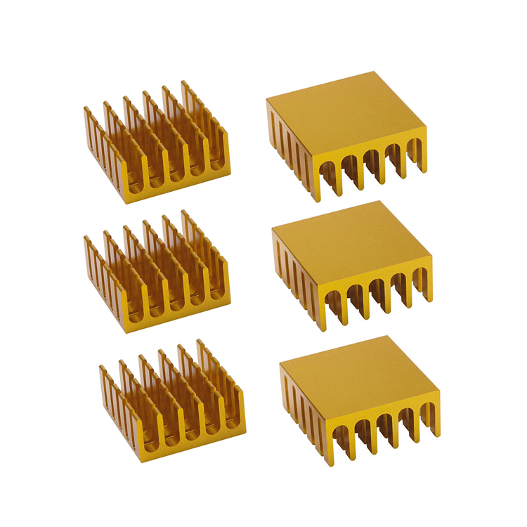
Industrial power supplies operate at unprecedented power densities, making thermal management a primary point of failure rather than an afterthought. Selecting an inadequate or improperly specified heat sink leads to thermal throttling, accelerated component degradation, and catastrophic system failure in harsh operating environments. Engineers must move beyond guesswork and apply rigorous thermal analysis to ensure long-term reliability.
This guide details an objective, engineering-driven framework for evaluating and specifying the correct aluminum power supply heat sink based on thermal resistance requirements, alloy properties, and manufacturing constraints. You will learn how to balance volumetric limitations with cooling demands to optimize system performance.
Alloy Selection Matters: Balancing thermal conductivity with structural hardness (e.g., 6063 vs. 6061 aluminum) is critical to prevent deformation under thermal cycling.
Manufacturing Dictates Performance: Extrusion, skiving, and cold forging offer distinct trade-offs between fin density, thermal resistance, and unit cost.
Surface Treatments are Functional, Not Cosmetic: Utilizing an anodized heat sink significantly increases surface emissivity for natural convection and provides essential dielectric and anti-corrosion properties.
System-Level Integration is Mandatory: A high-performance heat sink will fail without proper Thermal Interface Material (TIM) specification and airflow management.
Thermal resistance dictates how effectively a component dissipates heat into the surrounding environment. Calculating the required thermal resistance ($R_{th}$) forms the foundation of any heat sink specification. The formula requires three primary variables: maximum allowable junction temperature ($T_j$), maximum ambient temperature ($T_a$), and total power dissipation in watts ($P_d$).
The equation $R_{th} = (T_j - T_a) / P_d$ provides the absolute maximum thermal resistance the system can tolerate. Engineers must subtract the thermal resistance of the component package and the thermal interface material from this total to isolate the required heat sink thermal resistance. Failing to account for these intermediate thermal barriers results in under-specified cooling solutions and premature component failure. For example, a power module dissipating 50W with a max junction of 100°C in a 50°C ambient environment requires a total system thermal resistance of 1.0°C/W. If the package and TIM account for 0.3°C/W, the heat sink must perform at 0.7°C/W or better.
Volumetric limitations heavily influence fin design and overall boundary conditions. Z-height restrictions in compact power supplies often force engineers to prioritize fin density over fin height, altering the manufacturing approach. Space constraints dictate whether the system can accommodate forced airflow or must rely entirely on natural convection.
Natural convection relies on buoyancy and emissivity, requiring wider fin spacing to prevent boundary layer interference. Forced airflow environments allow for tightly packed fins to maximize surface area. Industrial applications also introduce severe shock and vibration standards. Heavy heat sinks require robust mechanical mounting mechanisms directly to the chassis rather than relying on solder joints or thermal tape, which fail under continuous mechanical stress.
Base plate thickness determines heat spreading resistance. A base plate must be thick enough to distribute thermal energy evenly across all fins before localized hot spots develop directly above the power component. Insufficient base thickness renders the outer fins useless, drastically reducing the volumetric efficiency of the heat sink.
Optimal fin-to-gap aspect ratios depend entirely on the airflow environment. Laminar natural convection requires wider gaps to allow heated air to escape without choking the airflow path. Turbulent forced convection benefits from higher fin densities and narrower gaps, as the static pressure from cooling fans forces air through the restrictive channels, stripping heat away at a much higher rate.
Convection Type | Optimal Fin Spacing | Airflow Velocity | Primary Heat Transfer Mechanism |
|---|---|---|---|
Natural Convection | 6mm - 10mm | < 0.5 m/s | Buoyancy and Radiation |
Low-Speed Forced | 3mm - 5mm | 0.5 - 2.0 m/s | Laminar Convection |
High-Speed Forced | 1mm - 3mm | > 2.0 m/s | Turbulent Convection |
Material selection begins with comparing baseline thermal conductivity. Copper offers superior thermal conductivity at approximately 400 W/mK, while aluminum ranges between 200 and 237 W/mK depending on the specific alloy. Despite copper's thermal advantage, aluminum remains the dominant choice for industrial power supplies due to practical engineering constraints.
Aluminum features a significantly lower specific weight. This weight reduction is crucial for minimizing mechanical strain on printed circuit boards (PCBs) during shock and vibration testing. Copper is strictly necessary only in extreme high-heat-flux scenarios where spatial constraints prohibit a larger aluminum footprint, such as dense server power modules or specialized laser diode cooling.
The 6000-series alloys serve as the standard for industrial cooling applications. Alloy 6063 provides excellent thermal conductivity (around 200 W/mK) and extrudes easily, making it the default choice for complex fin profiles. Alloy 6061 offers higher tensile strength and superior machinability but sacrifices a small percentage of thermal conductivity.
Engineers must avoid the pure aluminum risk. While pure aluminum grades like 1050 or 1070 boast thermal conductivities approaching 230 W/mK, they suffer from extremely low yield strength. Continuous thermal stress and high mechanical mounting pressure cause pure aluminum to warp and deform over time. This deformation breaks the thermal contact between the component and the heat sink, leading to rapid thermal runaway.
Alloy Grade | Thermal Conductivity (W/mK) | Yield Strength (MPa) | Primary Application |
|---|---|---|---|
6063-T5 | ~200 - 209 | ~145 | Standard Extrusions |
6061-T6 | ~167 - 180 | ~276 | Machined Components |
1050 (Pure) | ~220 - 230 | ~28 | Low-stress stamped fins |
Extrusion serves as the baseline manufacturing method for high-volume applications. Heated aluminum billets are forced through a steel die to create continuous profiles. This process yields excellent structural integrity and consistent thermal performance across large production runs.
The primary physical limitation of extrusion is the extrusion ratio, defined as the fin height divided by the gap between fins. Standard extrusion processes typically max out at a 10:1 or 12:1 ratio. Pushing beyond these limits causes the die teeth to break under pressure. This restriction limits the maximum fin density achievable, making standard extrusions unsuitable for applications requiring extreme surface area in confined volumes.
Skiving utilizes a precision cutting tool to slice thin layers from a solid block of aluminum, folding them upright to form fins. This method achieves ultra-thin fins and exceptionally high surface area-to-volume ratios that surpass extrusion limits.
Because the fins and base remain a single, continuous piece of material, skiving eliminates the thermal interface resistance found in bonded or pressed-fin assemblies. Heat flows seamlessly from the base up into the fins without encountering microscopic air gaps or bonding agents. Skived designs are highly effective in forced convection environments where dense fin arrays are required.
Bonded fins accommodate oversized industrial applications where standard extrusion presses cannot meet the required width dimensions. Individual fins are machined or stamped and then inserted into grooves on a separate base plate. This allows engineers to mix materials, such as bonding aluminum fins to a copper base plate for enhanced heat spreading.
The critical drawback of bonded assemblies is the thermal penalty introduced at the joint. The epoxy, solder, or brazing agent used to attach the fins possesses a lower thermal conductivity than the base metal. This joint acts as a thermal bottleneck. Folded fin assemblies, created by bending continuous sheet metal into a corrugated pattern, face similar attachment challenges and require high-quality brazing to ensure reliable heat transfer.
Cold forging shapes aluminum under extreme pressure at room temperature. This process excels at creating pin-fin designs. Pin fins allow omnidirectional airflow, making them ideal for environments where the airflow direction is unpredictable or relies entirely on natural convection. Cold forging maintains the grain structure of the aluminum, preserving high thermal conductivity.
Die-casting involves injecting molten aluminum into a mold. While it allows for highly complex, net-shape geometries, it introduces severe thermal risks. The die-casting process traps microscopic air pockets within the metal, known as internal porosity. Air acts as a thermal insulator, severely degrading the overall thermal transfer efficiency of the component. Die-cast heat sinks generally exhibit lower thermal conductivity than their extruded or forged counterparts.
Bare aluminum oxidizes naturally, but applying an engineered anodic coating transforms the surface properties. Specifying an anodized heat sink fundamentally alters the physics of radiation heat transfer. Black anodizing increases surface emissivity from approximately 0.05 to 0.85 or higher. In natural convection setups, this drastically improves the heat sink's ability to radiate thermal energy into the surrounding environment.
Anodizing provides critical secondary benefits for industrial applications. The aluminum oxide layer significantly increases surface hardness, protecting against scratches and handling damage. More importantly, the anodic layer acts as an electrical insulator. These dielectric properties prevent accidental short circuits if a component or wire contacts the heat sink. The coating also establishes a robust baseline of corrosion resistance against ambient humidity.
Certain industrial applications require alternative surface treatments. Chromate conversion coatings, such as Alodine or Iridite, provide corrosion resistance while maintaining electrical conductivity. This is essential when the heat sink must serve as a grounding path for electromagnetic interference (EMI) or radio frequency interference (RFI) shielding.
Extreme industrial environments, such as marine applications or chemical processing plants, demand superior protection. Electroless nickel plating offers exceptional resistance to corrosive gases and salt spray. However, engineers must account for the resulting impact on thermal resistance. Nickel plating adds a layer of metal with lower thermal conductivity, slightly impeding the heat transfer rate compared to bare or anodized aluminum.
Microscopic imperfections exist on all machined surfaces. When a heat sink mates with a power component, these imperfections create air gaps that act as severe thermal insulators. Thermal Interface Materials (TIMs)—including greases, silicone pads, and phase-change materials—are mandatory to fill these voids and establish a continuous thermal path.
Mounting pressure dictates the effectiveness of the TIM. Insufficient pressure fails to compress the TIM adequately, leaving air gaps and resulting in high thermal resistance. Excessive pressure forces too much TIM out of the joint and causes PCB warping or permanent deformation of the heat sink base. Engineers must specify precise torque values and utilize spring-loaded mounting hardware to maintain consistent pressure during thermal expansion and contraction.
Clean both the component and heat sink mating surfaces with isopropyl alcohol to remove oils and particulates.
Apply the specified TIM according to manufacturer guidelines, ensuring even coverage without excess material.
Position the heat sink squarely over the component to avoid smearing the TIM.
Tighten mounting hardware in a cross-pattern to apply even pressure across the die.
Verify final torque specifications using a calibrated torque screwdriver.
Deploying an industrial heat sink in humid, salt-fog, or corrosive atmospheres introduces the risk of galvanic corrosion. This occurs when aluminum mates with dissimilar metals, such as copper busbars or bare steel fasteners, in the presence of an electrolyte like condensation.
The aluminum acts as an anode and rapidly corrodes, compromising both structural integrity and thermal performance. Mitigation strategies require breaking the electrical connection between the dissimilar metals. Engineers must utilize dielectric isolation washers, specify zinc-plated or stainless-steel hardware, and apply appropriate conformal coatings to prevent moisture ingress at the mounting joints.
An optimized electronic heat sink fails if the cooling air never reaches the fins. Airflow bypass occurs when forced air takes the path of least resistance around a dense fin array rather than pushing through the restrictive channels. High fin density increases static pressure, encouraging air to flow over the top or around the sides of the heat sink.
System-level integration requires strict airflow management. Enclosure ducting and baffling are necessary to force air engagement with the heat sink. Plenums must be designed to direct fan output directly into the fin channels, ensuring the calculated thermal resistance is actually achieved in the physical application.
Calculate your exact thermal resistance requirements based on maximum junction temperature and power dissipation before selecting any hardware.
Measure your physical enclosure constraints to determine if you need a high-density skived fin design or a standard extruded profile.
Specify black anodizing for natural convection environments to maximize radiation heat transfer and protect against corrosion.
Select a high-performance thermal interface material and define strict torque specifications for the mounting hardware.
Run computational fluid dynamics (CFD) simulations to verify airflow paths and eliminate bypass issues before physical prototyping.
A: Alloy 6063 is generally the best choice for extruded heat sinks due to its optimal balance of high thermal conductivity (approx. 200 W/mK) and excellent extrudability for complex fin profiles. Alloy 6061 is preferred when higher structural strength or extensive CNC machining is required.
A: Black anodizing significantly increases the surface emissivity of the aluminum, drastically improving radiation heat transfer in natural convection environments. It also provides a hardened, electrically insulating surface that protects against corrosion and accidental short circuits.
A: Copper should be selected only in extreme high-heat-flux applications where severe spatial constraints prevent the use of a larger aluminum heat sink. Copper offers higher thermal conductivity but is significantly heavier and more difficult to machine.
A: Size is determined by calculating the required thermal resistance ($R_{th}$). Use the formula $R_{th} = (T_j - T_a) / P_d$, factoring in the maximum junction temperature, ambient temperature, and power dissipation. The resulting value dictates the necessary surface area and fin volume.
A: Deformation typically occurs when pure aluminum grades (like 1050) with low yield strength are subjected to continuous thermal cycling and excessive mechanical mounting pressure. Using 6000-series alloys prevents this structural warping.
A: Yes, extruded heat sinks work well in forced convection if the fin spacing is optimized for the fan's static pressure. However, if extreme fin density is required to maximize surface area, skived or folded fin designs may be necessary.
A: Standard extrusion processes are limited by the extrusion ratio (fin height to gap width), which typically maxes out around 10:1 or 12:1. Exceeding this ratio risks breaking the extrusion die, limiting the maximum achievable fin density.