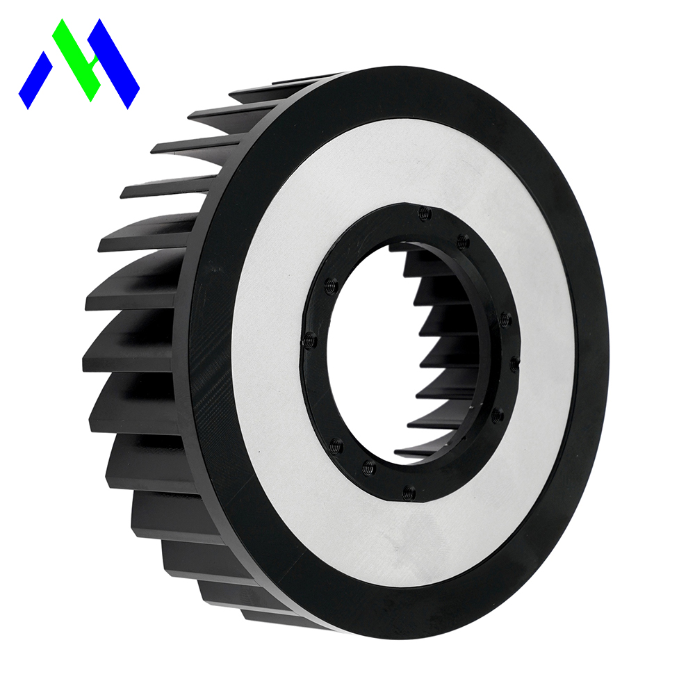
High-power electronics—such as EV traction inverters, server racks exceeding 1kW per unit, and industrial laser systems—have surpassed the thermal dissipation limits of traditional forced-air cooling and standard off-the-shelf cold plates. Specifying an inadequate thermal management system leads to thermal throttling, catastrophic junction failure, or system leaks. Off-the-shelf solutions frequently force unacceptable compromises in form factor, pressure drop, or mounting hole locations. Transitioning to a custom liquid cooling heat sink requires a rigorous evaluation of thermal resistance, fluid dynamics, material compatibility, and manufacturing methodologies to ensure long-term reliability and scalable production. Engineers must navigate complex trade-offs between hydraulic performance and thermal extraction, ensuring the final design aligns perfectly with the specific spatial and operational constraints of the target application.
Thermal vs. Hydraulic Trade-offs: Maximizing heat transfer through complex internal micro-channels inherently increases pressure drop, requiring careful alignment with system pump capacities.
Material Selection Dictates Chemistry: Choosing between an aluminum heat sink and a copper base impacts not only weight and cost but also dictates strict coolant chemistry requirements to prevent galvanic corrosion.
Manufacturing Method Defines Performance Limits: The choice between a CNC machined heat sink, vacuum brazing, or friction stir welding (FSW) dictates the allowable complexity of internal flow paths and maximum operating pressures.
Design for Manufacturability (DFM) is Critical: Early collaboration with a manufacturing partner mitigates the risks of un-machinable geometries, ensuring a seamless transition from prototype to high-volume production.
Define the exact thermal and spatial thresholds where standard air-cooled or catalog liquid-cooled solutions fail. High-performance systems require precise temperature control to maintain efficiency and prevent component degradation. When standard options cannot meet target junction temperatures under maximum load, a custom approach becomes necessary. Engineers must establish clear success criteria based on maximum allowable junction temperatures, ambient operating conditions, and available physical space within the enclosure. You need to map out the exact heat dissipation requirements for every active component on the board. Standard cold plates often feature generic internal channel routing that misses localized hot spots, leading to uneven cooling and premature component failure. A custom design allows you to route the coolant directly under the highest heat-generating components, ensuring uniform temperature distribution across the entire assembly.
High-performance skived copper or aluminum air-cooled heat sinks reach their limits when airflow requirements create excessive noise or demand impractical fan sizes. A dedicated water cooled heat sink provides superior thermal extraction without the acoustic and volumetric penalties associated with massive forced-air setups. Air cooling relies on the ambient air temperature and the surface area of the fins. As power densities increase, the required fin surface area grows exponentially, eventually exceeding the available physical space. Liquid cooling utilizes fluids with significantly higher heat capacities and thermal conductivities than air, allowing for much more compact cooling solutions. This transition is particularly critical in sealed enclosures where exchanging air with the outside environment is impossible due to ingress protection requirements.
Cooling Method | Typical Heat Flux Limit | Acoustic Impact | Volumetric Efficiency | Maintenance Requirements |
|---|---|---|---|---|
Forced Air Cooling | Up to 50 W/cm² | High (Fans required) | Low (Requires large fin area) | Filter cleaning, fan replacement |
Standard Cold Plate | 50 - 100 W/cm² | Low (Pump noise only) | Medium (Fixed geometries) | Coolant checks, leak inspections |
Custom Liquid Cooling | > 100 W/cm² | Low (Optimized flow paths) | High (Tailored to enclosure) | Coolant chemistry management |
Liquid cooling becomes mandatory when system power dissipation exceeds 1 kW or localized heat flux densities surpass 50-100 W/cm². At these levels, air cannot absorb and transport heat rapidly enough, leading to localized hot spots and rapid component failure. High-power IGBT modules, advanced microprocessors, and laser diodes frequently operate well above these thresholds. The thermal resistance of the interface materials and the heat sink base itself becomes a significant bottleneck. Liquid cooling mitigates this by bringing the cooling medium as close to the heat source as physically possible, often utilizing micro-channel structures to maximize the surface area in contact with the fluid. You must calculate the exact heat flux for each component to determine the necessary internal channel geometry and flow rates required to maintain safe operating temperatures.
Custom designs resolve packaging constraints in dense electronic enclosures where standard rectangular cold plates cannot physically fit or route coolant effectively. Tailored geometries allow engineers to route cooling channels precisely where needed, optimizing space utilization within tight chassis constraints. Modern electronic assemblies often feature irregular shapes, varying component heights, and strict keep-out zones for wiring and connectors. A custom solution can be machined to match the exact topography of the PCB, incorporating pedestals to contact components of different heights while avoiding sensitive areas. This level of integration reduces the overall footprint of the thermal management system, freeing up valuable space for additional electronics or reducing the overall size of the final product.
Calculate the required thermal resistance from the device junction to the liquid coolant to maintain safe operating margins. Lower thermal resistance ensures heat moves efficiently from the electronic component into the fluid stream, preventing thermal throttling during peak loads. The total thermal resistance is the sum of the junction-to-case resistance of the component, the case-to-sink resistance of the thermal interface material (TIM), and the sink-to-fluid resistance of the cold plate. You must minimize each of these values to achieve optimal performance. The sink-to-fluid resistance is primarily determined by the internal channel design, the fluid properties, and the flow rate. By optimizing the internal geometry, you can significantly reduce this resistance, allowing the components to operate at lower temperatures or handle higher power loads.
Determine the maximum allowable junction temperature for the critical components.
Calculate the total power dissipation under worst-case operating conditions.
Select a thermal interface material with appropriate thermal conductivity and thickness.
Determine the maximum allowable thermal resistance for the liquid cooling system.
Iterate the internal channel design and flow rate to meet the target thermal resistance.
The relationship between flow rate, turbulence, and pressure drop is non-linear. Evaluate the system's pump curve against the heat sink's hydraulic resistance. Excessive pressure drop strains pumps and reduces overall system efficiency, while insufficient flow compromises thermal performance. Increasing the flow rate generally improves heat transfer by increasing turbulence and reducing the boundary layer thickness within the channels. However, this comes at the cost of a higher pressure drop, requiring a more powerful pump. You must find the optimal balance between thermal performance and hydraulic efficiency. Complex micro-channel designs offer excellent heat transfer but generate significant pressure drops. Macro-channel designs have lower pressure drops but may not provide sufficient cooling for high-heat-flux applications. Careful analysis of the pump curve and the system's hydraulic resistance is essential to ensure reliable operation.
Surface flatness and roughness are critical to minimize TIM thickness and reduce interfacial thermal resistance. A poorly machined surface requires thicker TIM, which acts as an insulator and degrades overall cooling efficiency. The mating surface of the heat sink must be machined to strict tolerances to ensure maximum contact area with the electronic components. Typical flatness requirements are less than 0.001 inches per inch, with surface roughness values (Ra) optimized for the specific TIM being used. Phase change materials and ultra-thin thermal pads require exceptionally smooth surfaces, while thicker thermal greases can accommodate slightly rougher finishes. You must specify the required surface finish based on the selected TIM and the mechanical clamping method to ensure optimal thermal transfer.
Mounting force, spring-loaded screws, and clamping brackets affect surface contact, prevent board warpage, and optimize thermal interface material performance. Uneven clamping pressure leads to poor thermal contact and potential mechanical stress on sensitive electronic components. The mechanical design of the attachment system is just as important as the thermal design of the heat sink itself. You must ensure that the clamping force is distributed evenly across the entire mating surface, compensating for any manufacturing tolerances or thermal expansion. Spring-loaded mounting hardware provides consistent pressure over time, accommodating changes in TIM thickness or component dimensions. Careful consideration of the PCB layout and the location of mounting holes is necessary to prevent board warpage and ensure reliable long-term operation.
Factor in secondary heat exchanger performance and ambient air temperature limits to determine the maximum allowable fluid temperature entering the liquid cooling heat sink. The inlet temperature directly dictates the available thermal gradient for heat transfer. The entire cooling loop must be analyzed as a complete system. The heat absorbed by the cold plate must be rejected to the environment through a radiator or chiller. The performance of this secondary heat exchanger determines the temperature of the coolant returning to the cold plate. If the ambient air temperature is high, the radiator will be less effective, resulting in a higher coolant inlet temperature. You must account for these system-level variables when designing the internal channels and specifying the required flow rates to ensure the components remain within their safe operating limits under all conditions.
Evaluate the use of aluminum alloys for their high strength-to-weight ratio, lower raw material cost, and suitability for water-glycol coolant mixtures. An aluminum heat sink provides excellent performance for most industrial applications while keeping system weight manageable. Aluminum 6061 and 6063 are commonly used due to their excellent machinability and weldability. These alloys offer a good balance of thermal conductivity and mechanical strength, making them ideal for complex CNC machined designs. Aluminum is significantly lighter than copper, which is a critical factor in aerospace, automotive, and portable equipment applications. Furthermore, aluminum is generally more cost-effective than copper, both in terms of raw material costs and machining time. However, aluminum requires careful coolant management to prevent corrosion, particularly when used in mixed-metal systems.
Analyze scenarios demanding copper for extreme heat flux applications. Copper offers superior thermal conductivity but introduces trade-offs in weight, cost, and machining difficulty compared to aluminum alternatives. Copper alloys, such as C10100 (Oxygen-Free Electronic) and C11000 (Electrolytic Tough Pitch), provide nearly double the thermal conductivity of standard aluminum alloys. This makes copper the material of choice for applications with extremely high localized heat fluxes, such as laser diodes and high-power RF amplifiers. The high thermal conductivity allows heat to spread rapidly away from the source, minimizing the temperature gradient within the base plate. However, copper is significantly heavier and more expensive than aluminum. It is also more challenging to machine, requiring specialized tooling and slower feed rates, which increases manufacturing costs.
Material Property | Aluminum (6061-T6) | Copper (C11000) |
|---|---|---|
Thermal Conductivity (W/m·K) | ~167 | ~388 |
Density (g/cm³) | 2.70 | 8.89 |
Machinability | Excellent | Fair to Good |
Corrosion Resistance (Water) | Requires Inhibitors | Good (Prone to oxidation) |
Relative Cost | Low | High |
Address the implementation risk of galvanic corrosion. Match heat sink materials with appropriate coolants and system loop materials to ensure long-term reliability and prevent catastrophic leaks. Galvanic corrosion occurs when dissimilar metals are in electrical contact within a conductive fluid. In a mixed-metal cooling loop, the less noble metal will corrode rapidly. To prevent this, you must carefully select the materials for all components in the loop, including the cold plate, pump, radiator, and fittings. Using a single material throughout the loop is the most effective way to eliminate galvanic corrosion. If mixed metals are unavoidable, you must use a dielectric coolant or a water-glycol mixture with robust corrosion inhibitors. Regular maintenance and coolant testing are essential to ensure the inhibitors remain effective over the life of the system.
Milling complex channel paths into a base plate and sealing it with a cover plate using FSW is the industry standard for high-reliability, leak-free aluminum cold plates. A CNC machined heat sink offers precise control over internal geometries. The CNC machining process allows for the creation of optimized flow paths, including variable channel widths, turning vanes, and localized micro-structures directly beneath high-heat components. Once the channels are machined, a cover plate is joined to the base using Friction Stir Welding. FSW is a solid-state joining process that creates a high-strength, leak-proof seal without melting the base material. This eliminates the risk of porosity and distortion associated with traditional fusion welding techniques. The resulting assembly is incredibly robust and capable of withstanding high operating pressures and severe thermal cycling.
Vacuum brazing creates highly complex, multi-layer micro-channel structures, ideal for ultra-compact, high-performance requirements. This method allows for intricate internal designs that maximize surface area for heat transfer. The process involves stacking multiple layers of machined or stamped metal sheets, separated by a thin layer of brazing alloy. The assembly is then heated in a vacuum furnace until the brazing alloy melts and flows into the joints via capillary action. Vacuum brazing produces exceptionally strong and clean joints, free from oxidation and flux residues. This technique is particularly well-suited for creating high-density micro-channel arrays that would be impossible to manufacture using traditional CNC machining. However, vacuum brazing requires specialized equipment and tight manufacturing tolerances, making it a more expensive option for low-volume production.
This cost-effective method creates straight internal channels in thick metal blocks. However, it has limitations regarding flow path optimization and can create dead zones where coolant velocity drops, reducing cooling efficiency. Gun drilling involves using a specialized drill bit to create long, straight holes through a solid block of material. Multiple holes can be drilled intersecting each other to create a continuous flow path. The ends of the holes are then plugged and welded or brazed shut. This method is relatively inexpensive and suitable for simple cooling requirements. However, the internal geometry is limited to straight lines, making it difficult to optimize the flow distribution or target specific hot spots. The intersecting holes can also create areas of low flow velocity, leading to localized boiling and reduced thermal performance.
Compare the high surface-area-to-volume ratio of micro-channels against the lower pressure drop of standard macro-channels. Micro-channels offer superior heat transfer but require higher pumping power. The choice between micro-channels and macro-channels depends on the specific thermal and hydraulic requirements of the application. Micro-channels, typically defined as having hydraulic diameters less than 1mm, provide a massive increase in surface area, significantly reducing the sink-to-fluid thermal resistance. This makes them ideal for cooling high-power density components like laser diodes and advanced microprocessors. However, the small channel dimensions create substantial frictional resistance, resulting in high pressure drops. Macro-channels offer lower flow resistance, allowing for the use of smaller, less expensive pumps, but they provide less surface area for heat transfer. You must carefully balance these competing factors during the design phase.
Computational Fluid Dynamics simulation is vital in designing manifolds and channel layouts that ensure uniform flow distribution. Eliminate low-velocity areas where localized boiling could occur, which drastically reduces thermal performance. Uneven flow distribution is a common problem in complex cold plate designs. If the coolant favors the path of least resistance, some channels may receive insufficient flow, leading to localized overheating. CFD analysis allows engineers to visualize the flow patterns and identify potential dead zones before manufacturing begins. By adjusting the manifold geometry, adding flow restrictors, or modifying the channel layout, you can ensure that the coolant is distributed evenly across the entire active area. This optimization process is critical for maximizing the overall thermal efficiency of the design.
Implement design practices to prevent the coolant from bypassing high-heat zones through loose internal tolerances or structural flexing. Proper sealing and tight manufacturing tolerances ensure coolant flows exactly where intended. Internal bypass occurs when the coolant finds a path around the intended cooling channels, often due to gaps between the base plate and the cover plate or flexing of the internal structures under pressure. This reduces the effective flow rate through the active cooling zones, compromising thermal performance. To prevent bypass, you must specify tight machining tolerances and ensure that the joining method provides a continuous, high-strength seal. In FSW designs, the weld path must be carefully planned to intersect all internal walls, preventing any cross-flow between adjacent channels. Structural analysis should also be performed to verify that the internal walls will not deflect under maximum operating pressure.
Mandatory quality assurance protocols include helium leak testing and proof pressure testing. These tests verify the structural integrity of the heat sink before deployment. A leak in a liquid cooling system can cause catastrophic damage to the electronic components it is designed to protect. Rigorous testing is essential to ensure the reliability of the final product. Proof pressure testing involves subjecting the cold plate to a pressure significantly higher than its maximum operating pressure, typically 1.5x to 2x, to verify its structural strength. Helium leak testing is a highly sensitive method used to detect microscopic flaws in the welds or brazed joints. The cold plate is pressurized with helium gas, and a mass spectrometer is used to detect any escaping gas. These tests provide confidence that the cold plate will operate safely and reliably in the field.
Repeated thermal expansion and contraction stress welds, brazed joints, and O-rings. Evaluate a design's fatigue life to ensure it can withstand the operational lifespan of the end product without developing leaks. Electronic systems often undergo thousands of power cycles during their lifetime, causing the cold plate to heat up and cool down repeatedly. This thermal cycling induces mechanical stress in the materials and joints due to differences in the coefficient of thermal expansion. Over time, this stress can lead to fatigue cracking and eventual failure. You must consider the fatigue life of the chosen materials and joining methods during the design phase. Finite Element Analysis can be used to simulate the thermal stresses and predict the fatigue life of the cold plate. Robust designs utilize materials with similar CTEs and employ joining techniques that minimize stress concentrations.
Address the risk of micro-channel clogging. Specify appropriate system-level filtration based on the smallest internal channel dimension to maintain consistent flow rates and thermal performance over time. Micro-channel designs are particularly susceptible to clogging from particulates in the coolant. Even microscopic debris can block a channel, reducing the flow rate and causing localized overheating. To mitigate this risk, you must implement a robust filtration system within the cooling loop. The filter's pore size must be significantly smaller than the smallest internal dimension of the cold plate. Regular maintenance and filter replacement are essential to ensure the long-term reliability of the system. Additionally, the entire cooling loop must be thoroughly cleaned and flushed before operation to remove any manufacturing debris or contaminants.
A custom liquid cooling heat sink is a critical system-level investment required to unlock the full performance and lifespan of high-power electronics. Evaluate manufacturing partners based on their in-house thermal simulation capabilities, precision CNC machining capacity, and verifiable quality control protocols. Compile your thermal load profiles, maximum allowable pressure drops, and 3D spatial envelopes, and contact a specialized thermal engineering team for a Design for Manufacturability review.
Compile a comprehensive thermal load profile detailing the heat dissipation of all critical components.
Define the maximum allowable pressure drop and identify the system pump specifications.
Establish the 3D spatial envelope and identify all mounting hole locations and keep-out zones.
Select a manufacturing partner with proven expertise in CNC machining, FSW, and thermal simulation.
Initiate a Design for Manufacturability review to optimize internal channel geometries and reduce production risks.
A: Lead times vary based on complexity and manufacturing method, typically ranging from 4 to 8 weeks for CNC machined prototypes. Vacuum brazed assemblies may require longer lead times due to specialized tooling and furnace scheduling.
A: Use compatible materials throughout the cooling loop and employ inhibited coolants designed to prevent ion exchange between dissimilar metals. Avoid mixing copper and bare aluminum in the same fluid path without robust dielectric fluids.
A: Maximum pressure depends on the construction method; FSW and vacuum brazed plates can often withstand operating pressures exceeding 100 PSI. Burst pressures can exceed 300 PSI depending on the wall thickness and internal support structures.
A: Choose CNC machining for low to medium volumes requiring complex internal channels, tight tolerances, or specific material properties not suitable for extrusion. Machining allows for rapid iteration without expensive hard tooling.
A: Lower surface roughness improves contact with the heat source, allowing for thinner TIM layers and reducing overall thermal resistance. A smoother surface minimizes microscopic air gaps that act as thermal insulators.