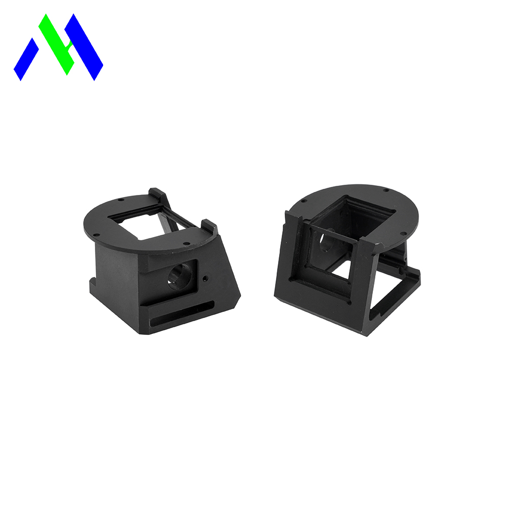
Anodizing is not just a simple cosmetic finish applied at the end of manufacturing. It acts as a highly controlled metallurgical process. It permanently alters your part dimensions, exposes poor machining practices, and dictates final component performance. You cannot treat it as an afterthought. Approaching procurement without properly factoring in dimensional growth, alloy composition, or precise pre-machining preparation leads directly to disaster. You will face immediate tolerance failures, frustrating color mismatches, and severely compromised mechanical assemblies in the field.
This guide exists to solve these critical engineering blind spots. We will provide engineers and procurement teams with a strict, evidence-based framework. You will learn how to properly evaluate, specify, and source high-quality aluminum CNC milling parts. Follow these proven principles to guarantee first-pass yield. You will ensure your industrial assemblies deliver reliable, highly predictable performance every time.
Anodize coatings grow 50% outward and 50% inward; pre-machining tolerance compensation is non-negotiable.
Alloy selection directly impacts coating success—high-copper alloys require different processing than standard 6061.
Improper CNC milling parameters (excessive heat, oil-based coolants) cause hidden "white-layer" defects that ruin anodic adhesion.
Proper engineering drawing callouts (e.g., MIL-A-8625) and defining rack mark locations are critical for vendor accountability.
Not all aluminum behaves predictably in an anodizing bath. You must evaluate material based on mechanical need versus finish quality. Selecting the wrong alloy creates surface inconsistencies. It compromises both structural integrity and visual aesthetics. We categorize these solutions carefully to ensure optimal results.
Engineers consistently rely on 6061 aluminum CNC milling parts for general industrial applications. This alloy offers the best balance of machinability and uniform anodic layer growth. It contains magnesium and silicon. These elements react predictably during the electrochemical process. 6061 takes dyes evenly. It serves as the top choice for consistent color matching across large production batches.
Aerospace and defense sectors demand extreme tensile strength. Here, 7075 aluminum machining becomes strictly necessary. However, 7075 contains high levels of zinc and copper. These elements slow down oxide layer growth. They also increase the risk of color spotting or uneven coating. Manufacturers must apply a specialized desmutting process to remove residual copper smut before anodizing. Failure to clear this smut results in a blotchy, rejected surface.
Sometimes dimensional stability and flatness take priority over absolute tensile strength. Cast tooling plates like MIC-6 provide the perfect solution. These materials undergo extensive stress-relieving processes during manufacturing. They excel for large, flat milling parts. You avoid clamping distortion entirely. You also prevent heat warping prior to anodizing. This guarantees a perfectly flat mating surface post-coating.
Alloy Type | Primary Benefit | Anodizing Behavior | Best Application |
|---|---|---|---|
6061-T6 | Balanced strength and machinability | Excellent uniformity, holds dye perfectly | Standard industrial parts, cosmetic housings |
7075-T6 | Maximum tensile strength | Prone to color spotting, slower layer growth | Aerospace brackets, high-stress gears |
MIC-6 / 5080 | Extreme flatness, zero internal stress | Good, but produces slightly matte finishes | Base plates, large fixture assemblies |
A perfect anodizing process cannot fix poor CNC milling. Surface defects multiply in the chemical bath. Anodizing magnifies every single tool mark, scratch, or chatter line. You must treat the machining phase as the ultimate foundation for coating success.
Excessive friction during milling alters the micro-structure of the aluminum. This phenomenon creates "white-layer" defects. This hardened, heat-damaged surface actively blocks the anodization process. The chemical bath cannot penetrate it. Vendors must use optimized cutting parameters to prevent this. They should maintain cutting speeds between 300 and 500 ft/min for 6061-T6. They must also utilize highly sharp carbide or TiCN-coated tooling to shear the metal cleanly rather than smear it.
Machining fluids play a critical role in surface prep. Oil-based coolants cause severe problems. They seep deep into the natural micropores of the aluminum. Standard washing cannot easily remove heavy oils. Residual oil causes obvious color variation and aggressive streaking after dyeing.
Specify water-soluble coolants: Mandate a 5-10% concentration mixture to prevent oil entrapment.
Require ultrasonic cleaning: Parts feature complex geometries and blind holes. Implement 20–40 kHz ultrasonic cleaning to blast microscopic debris out of internal threads.
Deionized water rinsing: Final rinses must use deionized water to prevent mineral spotting before the parts enter the acid bath.
Milled parts often feature sharp 90-degree internal and external corners. This geometry behaves terribly during electrochemical processing. Anodic coatings do not build up evenly on sharp right angles. The coating struggles to bridge the extreme geometry, creating a micro-void at the apex. This leads directly to edge chipping during physical handling. You must explicitly require your machinists to radius or chamfer all sharp edges. A simple 0.010" to 0.020" edge break prevents these catastrophic coating failures entirely.
Selecting the correct coating depends on your exact wear requirements and tolerance budgets. You must evaluate the physical environment your parts will face. Industrial buyers generally choose between two primary anodizing specifications.
Type II serves as the global standard for basic corrosion resistance and cosmetic color. It utilizes a sulfuric acid bath operating at room temperature. The final thickness typically ranges from 0.0002" to 0.001". This thin layer accepts organic dyes beautifully. It provides excellent surface protection for indoor or mild outdoor environments.
Engineers specify Type III for severe wear applications. This hardcoat process drops the acid bath temperature to near freezing. It utilizes higher voltage to force a much thicker, denser oxide layer. Surface hardness frequently reaches 60-70 HRC. This rivals hardened tool steel. Thickness usually exceeds 0.001". Due to the dense pore structure, shops typically leave Type III undyed. It naturally presents a dark gray or bronze appearance.
You cannot ignore dimensional shifts. Anodic layers do not just sit on top of the metal like paint. They grow equally into the substrate and outward. We call this the 50/50 rule. If you specify a 0.002" Type III coating, it consumes 0.001" of the base aluminum. It simultaneously adds 0.001" to the outward surface dimension. On a cylindrical shaft, this adds 0.002" to the total outer diameter.
You must actively protect tight tolerances. The CAD model and machining instructions must specifically compensate for this growth. Follow these steps to ensure precision:
Identify critical dimensions: Locate all press-fits, bearing bores, and sliding surfaces on the drawing.
Calculate the required growth offset: Determine the exact outward build-up based on your chosen anodize type.
Adjust the machining nominals: Machine a tight bore exactly 0.002" oversize. It will shrink perfectly to nominal after the hardcoat builds inward.
Communicate the strategy: Explicitly state "Dimensions apply AFTER anodizing" on your engineering notes.
Ambiguous CAD notes lead directly to supplier disputes and rejected parts. Writing "anodize black" on a print invites failure. You must define the precise parameters. Proper documentation limits liability and ensures the vendor delivers exactly what you need.
You must use precise compliance language. Rely on established aerospace or military standards to remove all ambiguity. The industry universally recognizes MIL-A-8625. Write a strict callout.
Example: “Finish: Anodize per MIL-A-8625, Type II, Class 2, Black.”
This single line dictates everything. It defines the acid process (Type II). It dictates the dye requirement (Class 1 equals clear/undyed, Class 2 equals dyed). It also specifies the final color. This protects you during quality control disputes.
Aluminum acts as a tremendous electrical conductor. Anodized aluminum acts as a powerful electrical insulator. This catches many young engineers off guard. If your assembly requires electrical grounding, you cannot anodize the grounding interface. You must clearly demarcate precise masking zones on the drawing. The vendor will apply liquid masking or custom silicone plugs to these areas before dipping the parts.
Anodizing requires physical electrical contact. Parts must be clamped tightly with titanium or raw aluminum contacts during dipping. The electric current flows through these contact points. Consequently, these specific spots will not receive any anodize coating. They remain bare. You must clearly mark "Acceptable Rack Mark Locations" on non-cosmetic or non-critical surfaces. If you ignore this, the vendor might clamp the part on a visible cosmetic face. This causes immediate aesthetic rejections. Take control of racking locations up front.
How do you prove the vendor delivered industrial-grade anodizing? You cannot rely entirely on visual inspection. Substandard or "garage DIY" processing looks deceptively similar to professional work on day one. You need hard verification to ensure long-term reliability.
Professional setups use highly controlled environments. They apply high current density, approximately 12 amps per square foot. They utilize precise chilling equipment to maintain acid bath temperatures. This creates tight, uniform pores. In contrast, low-current, poorly chilled setups create soft, highly porous layers. These substandard coatings fail prematurely under mild abrasion.
You must empower your receiving team to verify quality immediately upon delivery. Do not wait for field failures to discover a bad batch of anodized CNC components. Implement these practical on-site acceptance tests.
Use a basic digital multimeter. Set it to measure continuity. Touch both probes directly to the anodized surface. A properly sealed anodic coating should show zero electrical continuity. The multimeter should remain silent. Any conductivity indicates a violently breached or improperly sealed layer. Reject these parts immediately.
Hardcoat Type III should easily resist basic scratching compared to bare aluminum. You can perform a discrete scratch test in a non-critical area using a standard steel pick. Visually, a proper seal should present a highly consistent matte or satin finish under natural light. You should see absolutely no iridescent streaking. Iridescence indicates severe chemical contamination during the sealing bath.
For critical aerospace or medical parts, basic shop tests fall short. You must request formal compliance testing data from your supplier. Require thickness verification using the ASTM B580 Eddy Current method. Require seal quality and coating adhesion verification using the ASTM D3359 cross-hatch tape test. A reliable manufacturing partner will supply these certifications willingly with every shipment.
Sourcing successful anodized CNC components requires moving surface treatments upstream. You must integrate these considerations directly into the early design and machining phases. Waiting until the parts sit on the shipping dock guarantees failure. By selecting the correct alloy, enforcing strict machining parameters, calculating dimensional growth, and applying rigorous quality tests, you eliminate uncertainty.
Before freezing your next design, engage with a specialized CNC machining partner. Request a comprehensive Design for Manufacturability (DFM) review. Use this review to confirm tolerance compensation, optimize tooling paths, and verify alloy compatibility. Taking these exact steps transforms anodizing from a risky finishing step into a highly predictable, value-driving engineering asset.
A: No. Anodizing conforms exactly to the existing surface finish. It magnifies defects. Heavy milling marks, chatter, and scratches will remain completely visible. Parts requiring a uniform, perfectly matte look must be bead-blasted prior to the anodizing process.
A: High copper and zinc content in 7000-series alloys acts unpredictably. These elements migrate to the surface during machining. They react poorly if the pre-anodize desmutting bath is not properly calibrated by the manufacturer to dissolve heavy copper residues.
A: Yes, but outward dimensional growth will tighten the thread pitch significantly. Machinists must use oversized taps (e.g., H-limit taps) during the initial CNC milling phase. This compensates for the inward layer growth and ensures standard fasteners fit perfectly post-anodizing.