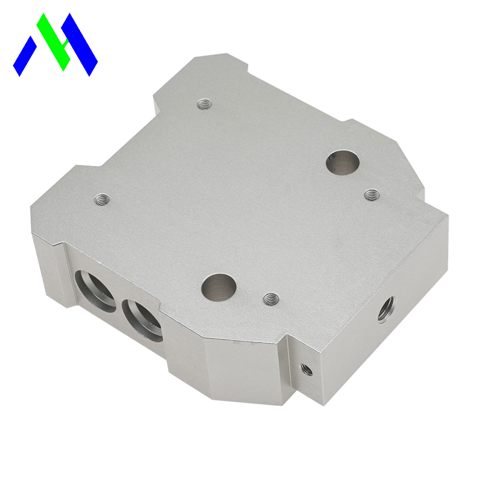
In aerospace manufacturing, we operate in a zero-margin-for-error reality. Even a microscopic dimensional inaccuracy can trigger a cascade of structural failures. These deviations cause severe aerodynamic inefficiencies. They create massive assembly roadblocks on the production floor. Worst of all, flawed parts lead to catastrophic Aircraft On Ground (AOG) events. Regulatory bodies like the FAA and EASA impose crippling fines for such non-compliance. To solve this, engineers rely on high precision CNC milling. This process serves as the undisputed industry standard. It achieves strict geometric consistency and micron-level accuracy. Crucially, it avoids the prohibitive tooling costs associated with traditional forging. Our goal is to equip engineering and procurement teams with a clear evaluation framework. You will learn how to verify capabilities, understand material behaviors, and mandate strict quality controls. This guide helps you confidently select a supplier for critical structural flight components. You need verifiable data to mitigate supply chain risks effectively.
Tolerance Capabilities: Standard aerospace structural components reliably hold tolerances of ±0.001 inches (25 µm), with tighter controls available for critical mating surfaces.
Material Selection: Anodized aluminum CNC milling parts remain the backbone of airframe structures, balancing strength-to-weight ratios with superior corrosion resistance.
Risk Mitigation: Machining accuracy must be paired with stringent compliance (AS9100D, AS9102 FAI) and closed-loop inspection (CMM) to ensure traceability.
Vendor Evaluation: Sourcing goes beyond the RFQ; successful procurement requires evaluating a machine shop’s ability to handle thermal distortion, complex GD&T, and digital workflow integration.
Let us clearly define what "accurate" actually means in an aerospace context. We must rely on exact numerical benchmarks to build technical trust. Engineers cannot afford vague promises or estimates. Different aircraft zones demand distinct tolerance levels based on their operational stress.
For large structural components like bulkheads, fuselage frames, and wing ribs, standard accuracy hovers around ±0.001 inches (25 µm). However, fluid routing and hydraulic systems require significantly tighter controls. A tiny leak at high altitudes is disastrous. Engine components and fuel management systems often reach tolerances of ±0.0001 to ±0.0003 inches (2.5–7 µm). Furthermore, surface finish requirements typically range from 2 to 8 µm Ra. This exceptional smoothness prevents micro-fissures from forming. It also reduces destructive friction between mating moving parts.
To visualize this metric, consider a standard human hair. A hair measures about 70 microns thick. High-end aerospace milling routinely cuts metal to a mere fraction of that width. We achieve perfection that remains entirely invisible to the naked eye.
Yet, true precision is not just about crafting one flawless prototype for a trade show. It requires maintaining identical geometric properties across full production runs of thousands of parts. True accuracy completely eliminates the need for manual fitting, filing, or shimming during final assembly. It ensures absolute interchangeability.
Component Type | Standard Tolerance (Inches) | Metric Equivalent (µm) | Surface Finish (Ra) |
|---|---|---|---|
Structural (Bulkheads, Ribs) | ±0.001 in | 25 µm | 3.2 - 8.0 µm |
Fluid & Hydraulic Fittings | ±0.0005 in | 12.5 µm | 1.6 - 3.2 µm |
Engine Components | ±0.0001 - ±0.0003 in | 2.5 - 7 µm | 0.4 - 1.6 µm |
Aluminum remains uniquely suited for aerospace structural integrity. The industry heavily relies on the 7075, 6061, and 2024 series alloys. These specific grades offer incredible thermal management properties. They dissipate heat rapidly during flight. More importantly, they provide a superior strength-to-weight ratio. Lighter planes consume significantly less fuel. This directly improves flight range and payload efficiency.
However, raw aluminum cannot survive extreme atmospheric conditions. High-altitude moisture, salt spray, and fluctuating temperatures degrade unprotected metal rapidly. We must apply advanced surface treatments to every part. This absolute necessity makes anodized aluminum CNC milling parts the gold standard for airframes. The anodic layer significantly improves overall fatigue life. It forcefully prevents galvanic corrosion when aluminum touches dissimilar metals. Furthermore, the anodized coating ensures essential dielectric stability. It protects surrounding sensitive avionics from electrical interference.
Skeptics often raise a highly valid concern regarding post-machining dimensional shifts. Anodizing actually adds a microscopic layer to the part surface. It also penetrates the base metal slightly. This protective buildup alters the final dimensions. Precision CNC programmers must calculate and offset these shifts during the pre-machining phase. If a shop ignores the anodic layer thickness, the final finished part will fail its CMM inspection.
Best Practices for Anodizing Tolerances:
Communicate specific finish requirements and layer thicknesses before the first cut.
Use Type III Hardcoat anodizing for high-wear structural areas like landing gear brackets.
Specify precise masking areas where electrical grounding conductivity remains required.
Account for thread pitch changes when anodizing tapped holes to prevent assembly seizing.
Achieving aerospace perfection is incredibly difficult in practice. We must acknowledge the harsh physical limitations of cutting hard metals. Milling aerospace CNC milling parts introduces severe thermal warping and mechanical stress. Fast tool rotation generates intense localized heat. This heat causes severe stress-hardening within the raw aluminum billet. If a machinist cuts too aggressively, unrelieved internal stress warps the final geometry hours after it leaves the machine.
To combat this, aerospace engineers use rigorous Tolerance Stack Analysis. Complex aerospace assemblies feature numerous parallel and perpendicular surfaces spanning large structural plates. A tiny deviation on one feature compounds rapidly across the entire part. We rely on strict Geometric Dimensioning and Tolerancing (GD&T) protocols. GD&T isolates specific features to prevent these compounding errors. It clearly defines the allowable variation for form, orientation, and location.
Multi-axis machining provides the ultimate physical solution here. Utilizing advanced 5-axis CNC equipment mitigates human error dramatically. Operators do not need to manually unclamp, rotate, and reposition the workpiece. Instead, the machine handles complex, thin-walled geometries in a single, continuous setup. The cutting tool approaches the part from any angle seamlessly. This advanced method drastically reduces run-out errors. It eliminates realignment deviations entirely, preserving the GD&T framework.
Common Mistakes to Watch Out For:
Ignoring localized heat buildup during aggressive deep-pocket milling.
Failing to rough-cut the geometry and let the material rest before executing final finishing passes.
Relying on traditional 3-axis setups for parts requiring complex undercut features, leading to multiple fixture errors.
Using incorrect coolant strategies that shock the metal thermally.
Quality control acts as your primary operational risk management tool. Unverified parts lead to grounded fleets immediately. They expose manufacturers to massive financial liabilities and legal action. You cannot guess or estimate when human lives are at stake at 30,000 feet. Every single structural component demands absolute, verifiable traceability from raw billet to final installation.
A reliable supplier must provide non-negotiable documentation. This paperwork proves their capability and process consistency unequivocally.
AS9100D Certification: This serves as the absolute baseline for aerospace quality management. It expands on standard ISO 9001 with strict, aviation-specific safety and risk requirements.
First Article Inspection (AS9102 FAI): This standardized document provides undeniable proof of process stability. You must review and approve the FAI report before authorizing any mass production run.
Mill Test Certificates (MTC) & NADCAP: MTCs ensure the raw aluminum's chemical authenticity. NADCAP certification guarantees the proper, standardized execution of critical thermal and surface treatments.
Modern aerospace shops integrate sophisticated closed-loop inspection processes. They use automated Coordinate Measuring Machines (CMMs) stationed right on the climate-controlled shop floor. CMMs verify complex GD&T callouts down to the single micron. Additionally, Non-Destructive Testing (NDT), such as ultrasonic scanning or dye penetrant inspection, verifies internal material integrity. We can find hidden voids, micro-cracks, or inclusions without damaging the actual finished component.
Sourcing flight-critical structural components goes far beyond sending out a mass RFQ. Buyers must thoroughly audit vendors on operational metrics far beyond unit price and quoted lead time. You need a highly capable, long-term manufacturing partner.
First, evaluate their prototyping agility versus their production scaling logic. A strong manufacturing partner executes rapid prototyping for early engineering design iterations. More importantly, they must seamlessly transition those prototypes to high-volume production. They should use the exact same digital toolpaths and fixturing strategies for both phases. This strict control ensures the mass-produced part mirrors the approved first article prototype perfectly.
Next, look deeply for Aerospace 4.0 readiness. The most reliable anodized aluminum machined parts come from digital-first machine shops. They utilize advanced digital twins. These virtual simulations mathematically model the entire machining process before any physical metal is cut. Digital twins accurately predict tool wear, chatter, and thermal distortion. Furthermore, automated tool-path optimization software guarantees maximum cutting efficiency. It drastically lowers scrap rates, extends tool life, and keeps your project on strict schedule.
Capability Area | Standard Machine Shop | Aerospace-Grade Partner |
|---|---|---|
Quality Management | ISO 9001 Compliant | Fully AS9100D Certified, NADCAP Approved |
Inspection Capabilities | Manual Calipers, Micrometers, Hand Gauges | Automated 5-Axis CMM, Ultrasonic NDT, Laser Scanning |
Workflow & Technology | Manual G-Code Edits at the Machine Controller | Digital Twin Simulation, 5-Axis Single Setup, IoT Tracking |
Traceability | Basic Material Receipts | Full AS9102 FAI, Mill Test Certificates for every batch |
High-precision aerospace manufacturing transcends the simple act of cutting metal. It functions as an intricate ecosystem of digital accuracy. It demands advanced material handling, deep metallurgical understanding, and rigorous compliance tracking. To succeed in modern aerospace design, you must completely respect the micron. You must demand uncompromising, verifiable data from all your manufacturing partners.
Here are your next actionable steps to move forward:
Audit your current supplier’s AS9100D and NADCAP standing immediately.
Submit your complex 3D CAD models for a comprehensive Design for Manufacturability (DFM) review.
Request a limited trial run to definitively validate their 5-axis single-setup capabilities.
Mandate full AS9102 FAI documentation on all future structural prototypes before scaling.
Move decisively from vendor evaluation to active execution. Partner with a specialized, digitally integrated machining facility to safeguard your next aerospace assembly.
A: CNC milling provides superior surface finishes and guaranteed material density. Billet milling eliminates the microscopic porosity sometimes found in additive manufacturing. This makes milled parts far more resistant to structural fatigue. While 3D printing excels at rapid, complex lightweighting, CNC remains the mandatory standard for load-bearing airframe structures.
A: Typical lead times range from three to six weeks, depending on complexity and finishing requirements. This is drastically faster than casting or forging, which require months just to produce tooling. Digital CNC setups allow rapid iterations. This speed is vital for resolving emergency Aircraft On Ground (AOG) situations.
A: We utilize specialized high-speed, low-feed cutting strategies. Programmers design balanced toolpaths that distribute cutting forces evenly. Additionally, shops employ vibration-dampening workholding and 5-axis equipment. This prevents harmonic chatter, wall collapse, and thermal stress, ensuring the thin-walled geometry remains perfectly intact.