
Poor edge quality, out-of-tolerance cuts, and micro-cracking create compounding financial impacts in high-value metal manufacturing. When processing highly reflective or heat-sensitive alloys, engineers face a persistent tension. They must balance production speed, material yield, and strict dimensional accuracy. Achieving reliable outcomes requires a rigorous evaluation of laser physics, material-specific behaviors, and design-for-manufacturability rules. You must also assess vendor capabilities before committing to a production run. This approach ensures structural integrity and minimizes downstream processing delays. We see too many projects fail at the press brake because the initial cut profile ignored thermal distortion limits. By locking down kerf compensation and assist gas parameters early, you prevent scrap. A successful run depends on matching the right fiber optic wattage to the specific alloy grade. Let's break down the exact mechanical requirements and machine settings needed to produce flawless components on the shop floor.
Fiber lasers dominate high-speed aluminum and thin stainless applications due to their 1.06 µm wavelength absorption, while CO2 remains relevant for specific ultra-smooth edge requirements on thick plates.
Thermal distortion and Heat-Affected Zones (HAZ) are the primary failure points in precision CNC sheet metal parts; mitigation requires precise assist gas selection (nitrogen vs. oxygen) and optimized cutting parameters.
Design for Manufacturability (DFM)—specifically accounting for kerf width, minimum hole-to-thickness ratios, corner radii, and cut-to-bend spacing—is non-negotiable for reducing scrap rates.
Selecting a premium laser cutting service hinges on verifying their equipment wattage (e.g., 8kW to 10kW+ systems), physical bed capacity, downstream secondary operations, and ISO-compliant quality frameworks rather than just baseline per-hour pricing.
Precision manufacturing demands strict adherence to defined tolerance requirements and edge quality standards. Acceptable deviation ranges typically fall between ±0.005" and ±0.010" for high-precision fabrications. Surface roughness metrics dictate the final finish of the cut edge. You must define these parameters early to prevent part rejection during final assembly. Shop floor operators rely on calibrated calipers, micrometers, and coordinate measuring machines (CMM) to verify these dimensions against the original CAD models. If the initial cut deviates, every subsequent bending and welding operation will compound that error.
Differentiating between cosmetic and structural classifications prevents over-specifying tolerances. Cosmetic parts, like brushed stainless medical enclosures or architectural panels, require pristine edges and flawless surfaces. Purely structural components, such as internal brackets or heavy equipment frames, prioritize strength over visual perfection. Over-specifying tolerances on structural cnc sheet metal parts unnecessarily inflates production time. Engineers must clearly annotate blueprints to indicate which surfaces are cosmetic. This allows the machine operator to adjust feed rates and gas pressures accordingly, optimizing the cycle time without sacrificing necessary quality.
Material yield and scrap reduction metrics directly influence project viability. Establish baseline expectations for CAD nesting efficiency. Calculate the physical impact of kerf loss on expensive alloys to optimize sheet utilization. Efficient nesting minimizes waste and maximizes the number of usable parts per sheet. Modern CAM software uses advanced algorithms to rotate and interlock part geometries, often achieving material utilization rates above 80%. Operators must also account for the skeleton—the web of scrap metal left behind—ensuring it remains structurally sound enough to be safely removed from the machine bed without snagging the laser head.
Evaluate how laser-cut edge quality impacts downstream operations. Clean cuts minimize the need for manual deburring. They also facilitate automated hardware insertion, robotic welding, and uniform powder coating adhesion. Poor edge quality introduces bottlenecks, forcing operators to spend time grinding and prepping surfaces before secondary processing. A jagged edge with heavy dross accumulation will cause a press brake to bend the material unevenly. It will also contaminate a TIG weld pool, leading to porosity and weak joints. Getting the cut right the first time is the only way to maintain a predictable manufacturing schedule.
Understanding process mechanics helps engineers select the right cutting parameters. Fusion cutting, or the melt-and-blow method, relies on high-pressure nitrogen gas. A laser cutting service uses this gas to expel molten metal from the kerf rapidly. This process prevents oxidation and preserves the base metallurgical properties of the material. It remains the preferred method for processing stainless and aluminum alloys. The nitrogen acts as a shielding agent, cooling the cut zone and blowing the liquefied metal straight down through the bottom of the sheet. The resulting edge is bright, clean, and ready for immediate welding.
Flame cutting utilizes oxygen as an assist gas. This creates an exothermic reaction that significantly increases cutting speeds in carbon steels. The oxygen literally burns the metal, adding thermal energy to the cut zone. However, oxygen-assisted cutting degrades edge weldability in stainless alloys by introducing oxides. These oxides form a brittle layer on the cut surface. Welders must mechanically grind this layer away before striking an arc, otherwise, the weld will fail under stress. For this reason, we strictly avoid oxygen assist gas when processing high-grade stainless or aluminum components intended for structural applications.
Vaporization cutting requires extremely high energy density. The beam rapidly vaporizes the material rather than melting it. Operators typically use this method for non-metals or extremely thin metallic foils. It is less common for heavy-gauge metal components due to the massive energy input required to vaporize thick cross-sections. The focal point of the laser must be precisely calibrated to concentrate the energy into a microscopic spot. If the focal length drifts even slightly, the beam will melt the material instead of vaporizing it, leading to severe thermal distortion and ruined parts.
The standoff distance between the cutting nozzle and the material surface also plays a massive role in process mechanics. Capacitive height sensors constantly monitor this distance, adjusting the Z-axis in real-time to compensate for slight undulations in the sheet metal. If the nozzle dips too low, it risks colliding with a tipped-up part. If it rides too high, the assist gas loses its kinetic energy, failing to clear the molten metal from the kerf. Maintaining the optimal standoff distance ensures a consistent, dross-free cut across the entire sheet.
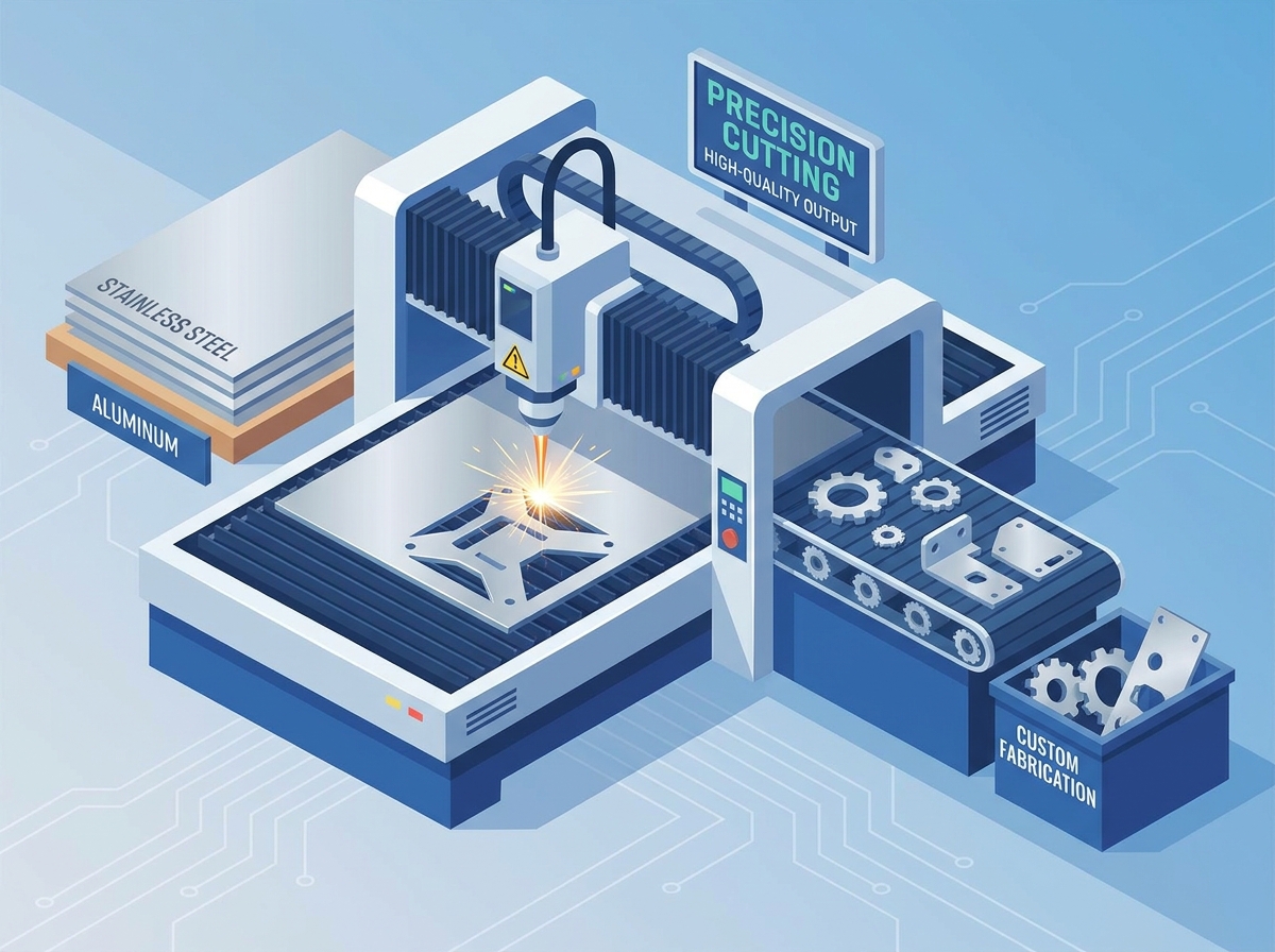
Fiber lasers dominate modern manufacturing, especially for aluminum laser cutting. They operate at a 1.06 µm wavelength, which metals absorb highly efficiently. This specific wavelength prevents catastrophic back-reflection damage when cutting highly reflective alloys like 5052 and 6061 aluminum. Older CO2 lasers struggled with aluminum because the beam would reflect off the shiny surface, travel back up the optics path, and destroy the internal mirrors. Fiber systems eliminate this risk entirely by delivering the beam through a solid-state fiber optic cable, cutting these materials much faster and safer.
When selecting technology for stainless steel laser cutting, modern high-wattage fiber lasers outperform traditional CO2 systems in speed and operating efficiency. Fiber lasers require less maintenance because they lack the complex gas blowers, vacuum pumps, and delicate mirror alignments found in CO2 resonators. They also consume significantly less electrical power. However, CO2 lasers sometimes provide a marginally smoother edge on exceptionally thick stainless plates. The longer wavelength of the CO2 beam creates a wider kerf, which allows the assist gas to flow more freely on plates thicker than 3/4 inch. Despite this minor advantage, high-power fiber systems have largely taken over the industry.
Equipment wattage determines maximum material thickness and cutting speed. Selecting the right power capacity ensures clean edges and minimizes thermal distortion. A shop running a low-wattage machine will have to slow down the feed rate to cut thick plates, which pumps excess heat into the part and causes warping.
System Power |
Best Suited For |
Maximum Aluminum Thickness |
Maximum Stainless Thickness |
|---|---|---|---|
4kW Systems |
High-speed cutting of thin-gauge materials. |
Up to 1/8" |
Up to 3/16" |
8kW to 10kW Systems |
Processing thick-gauge metals with clean edges. |
Up to 1/2" |
Up to 3/4" |
12kW+ Systems |
Heavy industrial capabilities with minimized taper. |
Up to 1" |
Up to 1" |
Physical bed dimensions constrain maximum sheet yields and raw part footprints. Standard table sizes include 5' x 10' or 6' x 12' configurations. Engineers must design parts that fit within these boundaries while allowing sufficient margins for clamping and nesting. Exceeding bed limits requires multi-piece assemblies and subsequent welding. You also have to consider the weight capacity of the shuttle tables. A 6' x 12' sheet of 1-inch thick stainless steel weighs thousands of pounds. The machine's automation system must be robust enough to load and unload these massive plates without stalling or damaging the material.
Processing 304 and 316 stainless steel requires careful management of the Heat-Affected Zone. Improper settings lead to carbide precipitation and dross accumulation along the bottom edge. Operators must use high-purity nitrogen assist gas (99.99%) to achieve an oxide-free, weld-ready surface. Any oxygen contamination in the gas line results in a dark, oxidized edge that requires mechanical grinding. We constantly monitor the gas delivery manifolds for micro-leaks. Even a tiny amount of ambient air entering the nitrogen stream will ruin the edge quality on a batch of medical-grade stainless components.
Aluminum alloys like 5052 and 6061 present different challenges due to high thermal conductivity. The material dissipates heat rapidly, increasing the tendency to warp or suffer micro-cracking on thin gauges. Mitigation strategies include utilizing pulse-cutting parameters, optimizing nesting layouts to distribute heat, and applying localized cooling techniques during the cut cycle. Instead of cutting all features on a single part sequentially, the programmer will instruct the laser head to jump around the sheet. This prevents any one area from absorbing too much thermal energy, keeping the aluminum flat against the machine bed.
Surface protection is critical when cutting pre-finished, polished, or brushed metals. Specialized laser-absorbent protective films prevent marring. Double-sided or fiber-compatible vinyl masks prevent peeling or bubbling during the piercing phase. Operators must ensure the masking material vaporizes cleanly without leaving adhesive residue on the part. Standard PVC masking films will release toxic chlorine gas when hit by a laser, destroying the machine's optics and endangering the operator. We only use certified fiber-laser-compatible masking tapes that melt back cleanly from the cut edge.
Low-power laser settings allow for precise marking and etching. Operators engrave part numbers, serialization barcodes, and bend-line alignments directly onto the workpiece. This occurs during the cutting cycle, eliminating the need for a secondary marking operation. It improves traceability and aids downstream assembly processes. The press brake operator uses these etched bend lines to align the tooling perfectly, eliminating the guesswork and reducing setup time. We also etch material grain direction arrows on brushed stainless parts to ensure the final welded assembly has a uniform cosmetic appearance.
Proper DFM practices reduce scrap rates and improve part quality. Engineers must account for kerf width compensation in their CAD models. The laser beam removes a small amount of material, typically ranging from 0.006" to 0.015" depending on thickness and focal length. CAM software usually handles this compensation, but designers must understand the limitation for tight-tolerance interlocking features. If you design a tab-and-slot joint without accounting for the kerf, the parts will fit together too loosely, requiring excessive filler metal during the welding phase.
Minimum hole diameters and feature spacing follow strict rules in sheet metal laser cutting. The minimum hole diameter must equal or exceed the material thickness. This 1:1 ratio prevents thermal blowout during pierce cycles. Adequate spacing between adjacent cut features prevents localized overheating, which can cause the web between cuts to melt and collapse. When the laser pierces thick plate, it ejects a fountain of molten slag. If the hole is too small, that slag has nowhere to go and blows back up into the nozzle, destroying the optics and ruining the hole geometry.
Avoiding sharp inner corners prevents stress concentrations. Specify minimum radii of at least 0.5 times the material thickness. This prevents cracking during secondary forming operations or field use under cyclic loading. Radiused corners also allow the laser head to maintain a constant feed rate, improving edge quality. When a laser hits a sharp 90-degree corner, the machine axes must decelerate to a complete stop before changing direction. This dwell time pumps excess heat into the corner, causing the material to melt away and leaving a blown-out, rounded edge anyway. Designing the radius in CAD prevents this issue.
Proximity of cuts to bend lines requires careful planning. Holes or slots placed too close to a bend will deform during press brake operations. Maintain a minimum distance of at least 1.5 times the material thickness plus the bend radius. Integrating tab-and-slot designs into cut parts reduces downstream welding setup times. Self-fixturing geometries eliminate expensive jigs and improve overall assembly accuracy. If a hole must be located near a bend line, we often laser-cut a small relief slit between the hole and the bend. This isolates the hole from the stretching forces of the press brake, keeping it perfectly round.
While lasers offer exceptional speed and precision, alternative processes serve specific niches. Waterjet cutting proves superior when processing ultra-thick materials above 1 inch. It is also mandatory for applications requiring a zero Heat-Affected Zone, such as specific aerospace-grade compliance standards. Waterjets cut without inducing thermal stress, preserving the temper of the base metal. However, waterjets are significantly slower than fiber lasers and generate a messy slurry of abrasive garnet and water that must be managed. They also leave a slight draft angle on the cut edge, which may require secondary machining for tight-tolerance fits.
Plasma cutting offers cost-efficiency for thicker, lower-precision structural plates. It cuts heavy steel rapidly but leaves a wider kerf and a rougher edge. Lasers remain necessary for high-precision components requiring tight tolerances and clean edges ready for immediate assembly. High-definition plasma systems have improved edge quality in recent years, but they still cannot match the pinpoint accuracy of a fiber laser. Plasma also introduces a massive Heat-Affected Zone, hardening the edge of the material and making it extremely difficult to drill or tap holes later in the production process.
Turret punching excels at repetitive, standardized geometries. Punching louvers, grilles, or high-volume standard holes is faster with a mechanical punch. However, lasers provide unmatched design flexibility and zero-tooling costs. You can change a laser cut profile instantly via software, whereas a punch press requires physical tooling changes. Punching also induces mechanical stress into the sheet, which can cause the material to bow or warp. Lasers exert zero physical force on the workpiece, allowing us to cut delicate, intricate webs without distorting the overall sheet.
Evaluating equipment sophistication ensures you partner with a capable vendor. Automated raw material loading, tower storage, and automatic nozzle changers directly lower overhead costs. These automated systems minimize lead times and eliminate human error during material handling. Facilities running lights-out automation offer superior scalability for large production runs. A shop with a fully automated material tower can run a 10,000-part order over the weekend without a single operator in the building. This level of automation guarantees consistent cycle times and protects the raw material from forklift damage and improper handling.
Favor vendors offering integrated secondary operations. Full-service custom sheet metal fabrication includes CNC bending, manual or robotic welding, hardware insertion, tapping, and finishing. Managing a single vendor for the entire component lifecycle reduces logistical friction and ensures accountability for final part dimensions. If you use one shop to cut the parts and another to bend them, you will inevitably face finger-pointing when the final assembly doesn't fit together. An integrated shop controls the entire process, adjusting the laser kerf to perfectly match their specific press brake tooling.
Quality assurance and traceability are paramount for critical applications. Verify the vendor's ability to provide Material Test Reports (MTRs) and First Article Inspections (FAI). ISO 9001:2015 certification demonstrates a robust quality framework. This compliance ensures chemical and mechanical traceability, which is strictly required for aerospace, medical, and defense contracts. We track every sheet of metal back to the original mill heat lot. If a part fails in the field, we can pull the records and identify exactly which batch of material it came from, which machine cut it, and who the operator was on that specific shift.
Audit your current CAD assemblies to verify that hole-to-thickness ratios meet the 1:1 minimum rule.
Adjust all internal corner radii to at least 0.5 times the material thickness to prevent stress fracturing.
Review the proximity of all cut features to planned bend lines to eliminate deformation during press brake forming.
Request a small prototype run from your selected vendor to validate edge-finish quality and dimensional accuracy before authorizing full production.
A: Modern high-wattage fiber lasers (10kW to 12kW) can cut stainless steel up to 1 inch thick. However, edge taper naturally increases as material thickness approaches the machine's maximum capacity. For precise, taper-free edges, keeping thickness under 3/4 inch on these systems is optimal.
A: High-pressure nitrogen acts as a shielding gas, producing a bright, oxide-free, and weld-ready edge. Using air or oxygen causes rapid oxidation, resulting in a discolored, rough edge that requires mechanical grinding before any subsequent welding can occur.
A: Kerf width typically ranges from 0.006 to 0.015 inches, depending on the material thickness, laser wattage, and focal length. Laser operators use CAM nesting software to automatically offset the cut path, compensating for this material loss to maintain strict part tolerances.
A: Yes. Operators use specialized laser masking films to protect the finish. Cutting from the reverse side and utilizing specific high-frequency pulse settings prevents the protective film from bubbling or peeling, ensuring the cosmetic surface remains pristine.
A: Preventing thermal distortion requires optimizing the nesting layout to distribute heat evenly across the sheet. Operators also use nitrogen pulse-cutting, integrate heat-sink practices, and employ tab-cutting strategies to keep the part stable and cool during the cutting cycle.
A: A dark edge indicates oxygen contamination within the cut zone. This occurs due to impure assist gas, leaks in the gas delivery line, or improper nozzle alignment. Utilizing certified high-purity nitrogen (99.99%) and maintaining equipment resolves this oxidation issue.
A: The standard rule requires the minimum hole diameter to be at least equal to the material thickness (a 1:1 ratio). Attempting to cut smaller features risks micro-piercing failure and thermal blowout, which destroys the hole's geometry and surrounding material.