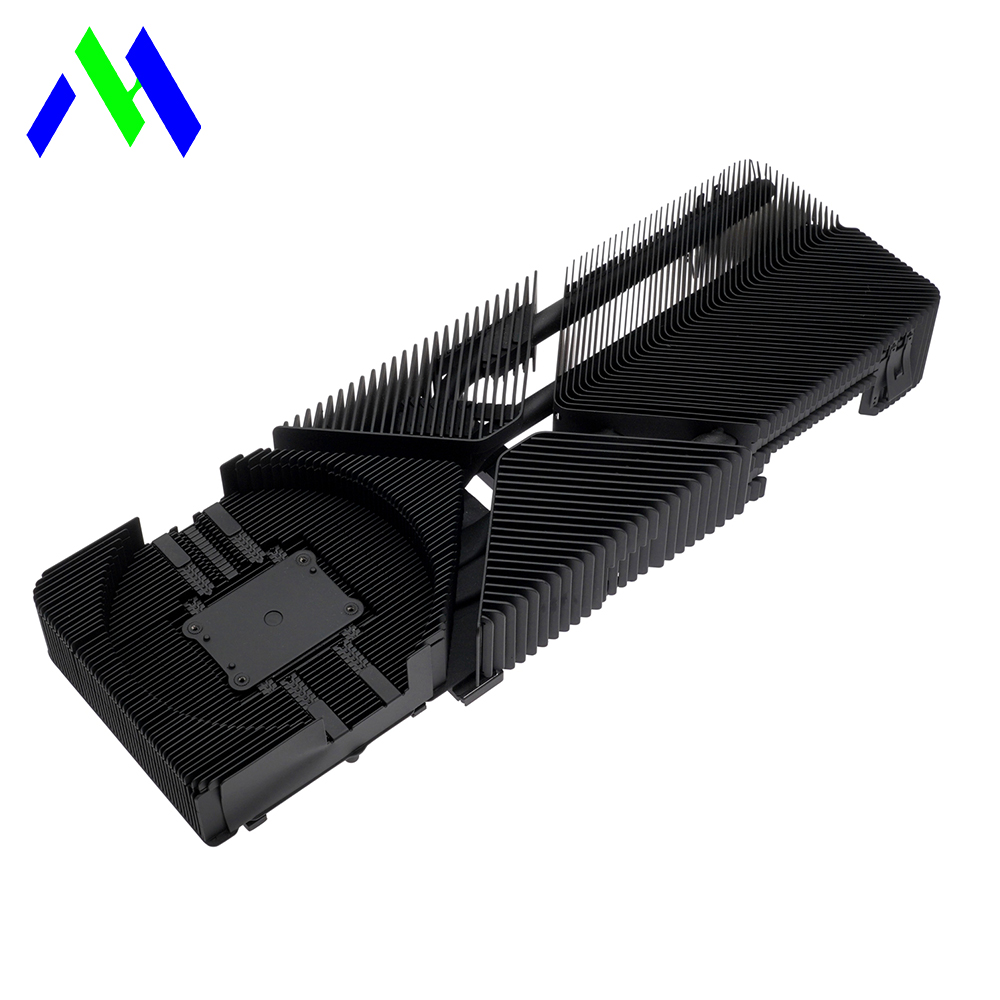
High-density electronics and high-performance semiconductors are increasingly constrained by thermal bottlenecks, rendering standard thermal management solutions obsolete. Off-the-shelf extruded or die-cast heat sinks often lack the geometric flexibility, localized mass, and mating surface precision required for advanced PCB layouts and high-wattage components. Designing a custom CNC machined heat sink allows engineers to dictate exact fin geometries, integrate complex mounting features, and achieve strict flatness tolerances. This guide breaks down the critical decision matrices—materials, tolerances, finishes, and manufacturability constraints—required to specify a high-yield, thermally optimized component.
Precision dictates thermal transfer: Achieving flatness tolerances of ±0.05 mm or better on semiconductor mating surfaces minimizes reliance on thermal interface materials (TIMs), directly reducing thermal resistance.
Material selection is a balance of conductivity and machinability: While copper offers superior thermal conductivity, an aluminum heat sink (typically 6061-T6) provides the optimal baseline for weight, cost, and rapid CNC cycle times.
Geometry is constrained by tooling: Deep, narrow fin channels improve surface area but increase the risk of tool chatter and fin distortion; aspect ratios must be balanced against CNC tooling realities.
Finishes impact both protection and performance: Specifying an anodized heat sink alters surface emissivity, significantly improving radiative heat dissipation in natural convection environments.
Standard extrusions limit fin density and base plate thickness variations due to the physical constraints of pushing hot metal through a steel die. Die casting introduces internal porosity, which degrades thermal conductivity and creates unpredictable hot spots. When you deal with high-power applications, you need a more robust and predictable approach to thermal management. Machining from a solid billet guarantees material density and allows for infinite geometric variations.
Monolithic CNC machining eliminates thermal resistance at the joints found in bonded or swaged fin assemblies. Every mechanical joint introduces microscopic air gaps. Even when filled with thermal epoxy, these joints impede heat flow. A solid billet transfers heat continuously from the base to the fin tips without interruption. The structural integrity benefits are substantial when the custom heat sink also serves as a structural chassis, enclosure wall, or mounting plate for PCBs. Integrating these functions into a single machined part reduces the overall bill of materials and eliminates tolerance stack-up issues during final assembly.
Standard profiles cannot adapt to uneven heat loads across a circuit board. Machining allows you to program variable fin pitches across the same part to optimize airflow based on fan placement or natural convection drafts. You can integrate heat pipe channels directly into the base for active cooling integration. Localized thicker base sections can be left directly over high-heat-flux components like CPUs or power transistors. This targeted mass absorbs thermal spikes effectively before spreading the heat to the fins. You dictate exactly where the mass goes based on your thermal simulation data.
Evaluating the metallurgical properties of common machining stock requires balancing thermal conductivity, material density, and machinability. The wrong material choice leads to excessive tool wear, warped parts, and poor thermal performance.
The 6061-T6 alloy is the industry standard for thermal components. It offers a strong balance of thermal conductivity at roughly 167 W/m·K. It boasts excellent machinability, producing short, manageable chips during heavy milling operations. An aluminum heat sink made from 6061-T6 provides a lightweight, efficient thermal path and responds predictably to anodizing. The 7075-T6 alloy provides higher tensile strength for structural applications where the heat sink acts as a primary load-bearing chassis. The trade-off includes slightly lower thermal conductivity (around 130 W/m·K) and higher raw material costs.
C11000 Electrolytic Tough Pitch Copper handles extreme heat loads efficiently. It delivers superior thermal conductivity around 388 W/m·K. However, significant trade-offs exist. Copper brings higher weight and increased raw material costs to the project. Its gummy nature makes it difficult to machine cleanly. The material tends to smear rather than shear, which increases CNC cycle times and accelerates tool wear. Machinists must use specialized sharp-edged tooling and heavy coolant flow to prevent built-up edge on the cutters.
Sometimes a single material falls short of thermal requirements while another breaks the weight budget. You can machine an aluminum body with precision-milled pockets and insert press-fit copper slugs directly under semiconductor nodes. This hybrid approach maximizes localized heat spreading where it matters most. It keeps the overall component weight manageable while delivering superior performance. The interference fit between the copper and aluminum must be tightly controlled to prevent thermal boundary resistance.
Material Grade | Thermal Conductivity (W/m·K) | Machinability Rating | Density (g/cm³) | Primary Application |
|---|---|---|---|---|
Aluminum 6061-T6 | 167 | Excellent | 2.70 | Standard thermal management, structural parts |
Aluminum 7075-T6 | 130 | Good | 2.81 | High-strength structural heat sinks |
Copper C11000 | 388 | Poor (Gummy) | 8.89 | Extreme heat flux, localized thermal nodes |
Copper C14500 (Tellurium) | 355 | Good | 8.94 | Complex copper geometries requiring faster machining |
Translating thermal requirements into manufacturable CAD models requires understanding machine limits. Engineers must design with the cutting tools in mind to avoid unmanufacturable features.
Straight fins allow rapid material removal during the milling process. Machinists utilize large-diameter side-action slotting cutters, such as slitting saws, mounted on horizontal arbors. This method clears channels quickly and efficiently. Omnidirectional pin fins require complex multi-axis milling operations. Pin fins improve airflow in unpredictable environments but take significantly longer to cut because an end mill must trace the profile of every single pin. Tool clearance requirements for side cutters are strict. You must avoid collisions with the heat sink base or adjacent mounting features when designing straight fin arrays.
The maximum practical fin height-to-gap aspect ratio dictates manufacturability. Standard CNC end mills typically handle 10:1 to 15:1 ratios safely. Exceeding these limits introduces severe implementation risks. Tool deflection and chatter occur when specifying overly thin or deep fins. This chatter ruins surface finishes, causes dimensional inaccuracies, and frequently destroys fragile cutting tools. If you need deeper fins, you must design wider gaps to accommodate thicker, more rigid cutting tools.
Standardizing corner radiuses is a necessity for efficient machining. Use standard dimensions like 1/8-inch or 1/16-inch for internal corners. This prevents the need for slow, custom-ground tooling or specialized Electrical Discharge Machining (EDM) operations. Standard radii keep production moving efficiently and reduce setup times. If a square internal corner is absolutely necessary for component clearance, consider designing a dog-bone relief cut to allow standard round end mills to clear the corner.
Machining threaded holes, counterbores, and alignment pins directly into the heat sink base eliminates secondary assembly steps. You can machine these features in the same setup used to face the mating surface. This ensures high-precision PCB alignment directly against the thermal transfer surface. True position tolerances between mounting holes and the thermal contact area can be held tightly when machined without refixturing the part.
Even microscopic air gaps act as thermal insulators. A perfectly flat surface is essential for efficient heat transfer from the component to the metal.
Dimensional tolerance and surface flatness are distinctly different engineering concepts. A part can be the correct thickness but severely warped. Establish strict baseline requirements for mating surfaces. Target an Ra of 0.8 µm to 1.6 µm. This ensures optimal contact with thermal pads or pastes. High-Speed Machining (HSM) techniques achieve ultra-smooth finishes directly off the mill. They often eliminate the need for post-machining grinding or lapping. Using a fly cutter or a large face mill with wiper inserts produces excellent surface finishes across wide base plates.
Holding tight tolerances of ±0.05 mm requires rigid CNC setups. Critical semiconductor mounting plates demand this level of precision. Specialized workholding, such as vacuum chucks, prevents part distortion during heavy roughing cuts. Clamping a thin base plate too hard in a standard vise will cause it to bow; once released, the machined surface springs back and loses its flatness. Over-tolerancing non-critical areas like fin tips wastes resources and machine time. Focus strict tolerances only on the thermal mating surfaces.
Rough machine the overall profile and fin channels, leaving 0.5 mm of material on the mating surface.
Release the workholding clamps to relieve internal material stresses introduced during roughing.
Re-clamp the part using light pressure or a vacuum fixture.
Perform a final light finishing pass on the mating surface to achieve the ±0.05 mm flatness requirement.
Secondary processes affect environmental resistance and thermal dynamics. The right finish enhances overall performance and protects the bare metal from oxidation.
Type II sulfuric and Type III hardcoat anodizing alter the surface chemistry of aluminum. They increase surface emissivity from roughly 0.05 for bare aluminum to about 0.85. Specifying an anodized heat sink drastically improves radiative cooling. This is crucial in natural convection environments where airflow is limited and radiation accounts for a larger percentage of total heat dissipation. The anodized layer also provides dielectric properties. This impacts electrical isolation for mounted components safely, preventing short circuits if a component touches the heat sink body.
MIL-DTL-5541 standard finishes offer specific benefits for aerospace and defense applications. They provide necessary corrosion resistance in harsh environments. Unlike anodizing, chem film maintains electrical conductivity across the surface. This is essential for grounding chassis components securely. If your heat sink must act as an EMI shield or a ground path, chem film is the correct specification.
Copper heat sinks often require robust environmental protection. Electroless nickel plating prevents rapid oxidation on copper surfaces. It also ensures solderability in advanced thermal assemblies where heat pipes or vapor chambers must be soldered directly to the machined base. This plating provides an even coating across complex fin geometries without pooling in the corners, unlike electrolytic plating methods.
Navigating the transition from prototype to low-volume production requires careful planning. Engineers must optimize designs for the machine shop to keep budgets under control.
Material utilization heavily impacts the final production cost. The ratio of raw billet sizing to finished part volume matters greatly. High material waste increases expenses rapidly, especially when machining copper. Setup times also drive costs upward. Multi-axis setups like 5-axis machining handle complex mounting features on multiple faces. However, they require expensive machine time and skilled programming. Designing the part to be machined in a single 3-axis setup drastically reduces the per-part cost.
Excessive material removal rates drive up machine hours. Hogging out deep channels takes considerable time. Optimize fin spacing for standard cutter diameters whenever possible. Use 1/8-inch or 1/4-inch slotting tools in the design phase. This allows single-pass pocketing. It eliminates secondary cleanup passes and speeds up production significantly. A CNC machined heat sink designed around standard tooling will always be cheaper and faster to produce.
Coordinate Measuring Machine (CMM) reporting is necessary for critical thermal parts. CMM verifies flatness and true position of mounting holes accurately. This guarantees PCB alignment during final assembly. Strict inspection protocols catch warping before components reach the assembly line. Specify exactly which surfaces require CMM probing on your engineering drawings using proper Geometric Dimensioning and Tolerancing (GD&T) callouts.
Finalize CAD models with clear datums on mating surfaces to ensure machining accuracy and proper inspection routines.
Separate critical tolerances on semiconductor contact areas from non-critical fin dimensions to avoid unnecessary manufacturing expenses.
Adjust fin gap widths to accommodate standard end mill diameters, ensuring single-pass machining and reducing cycle times.
Submit a comprehensive RFQ to a specialized CNC machining partner with proven thermal component experience and CMM capabilities.
A: Standard CNC end mills typically handle a maximum fin height-to-gap aspect ratio of 10:1 to 15:1. Pushing beyond these limits significantly increases the risk of fin vibration and tool chatter, which can ruin the surface finish and damage cutting tools.
A: Machining allows engineers to create complex geometries and variable fin pitches that extrusion dies cannot produce. It also achieves tighter flatness tolerances and integrates precise mounting features directly into the base plate.
A: Yes, anodizing significantly boosts thermal performance in natural convection environments. The process increases surface emissivity from roughly 0.05 to 0.85, which drastically improves the component's ability to dissipate heat through radiation.
A: Aluminum 6061-T6 is the optimal choice for most applications. It provides an excellent balance of thermal conductivity, machinability, and cost effectiveness. Alloy 7075-T6 is only recommended when higher structural strength is strictly required.
A: The mating surface typically requires a flatness tolerance of ±0.05 mm and a surface roughness of Ra 0.8 µm to 1.6 µm. This precision minimizes microscopic air gaps, ensuring optimal contact with thermal interface materials.