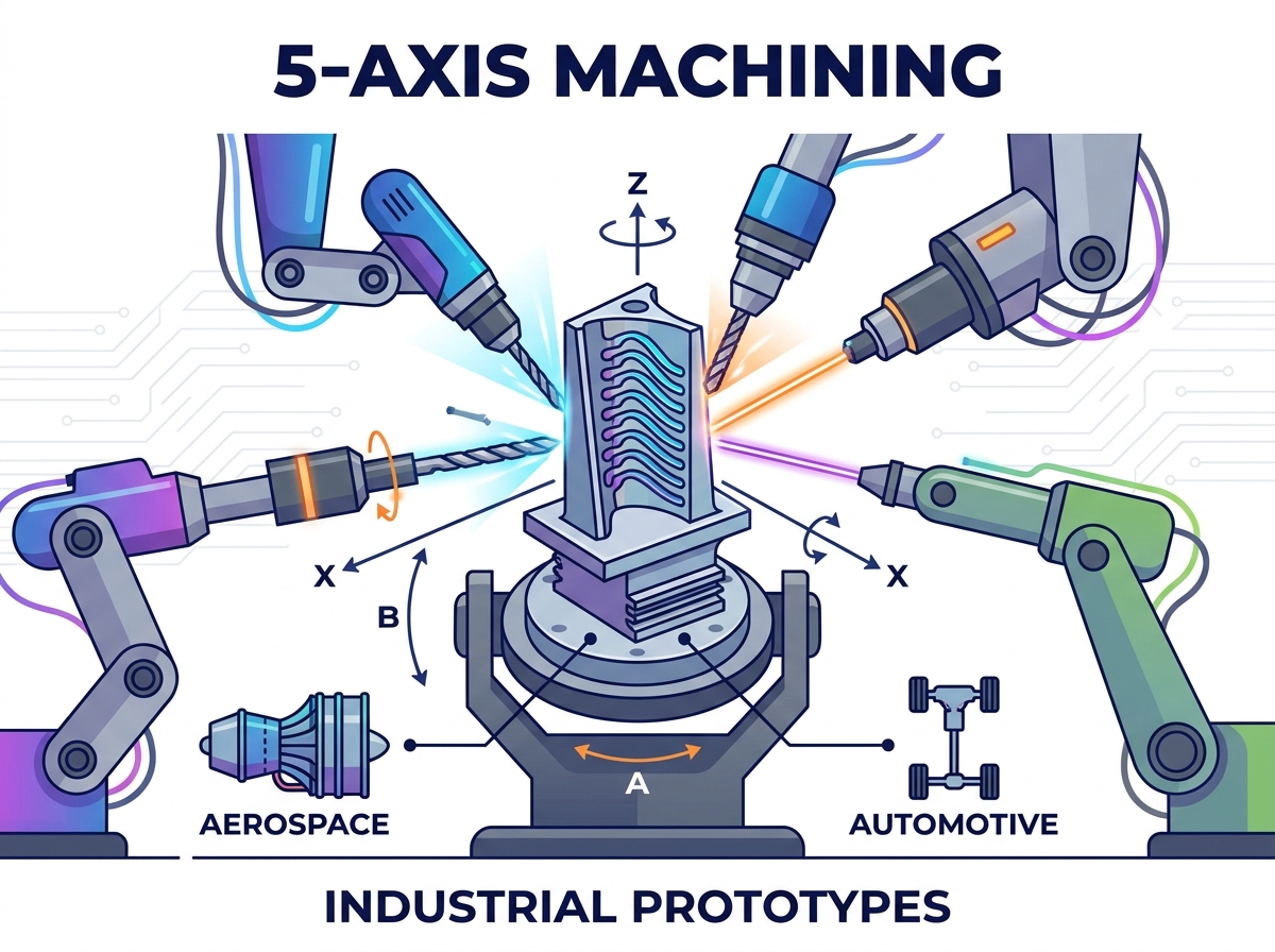
The escalating demand for tighter tolerances, organic geometries, and compressed timelines in rapid product development has pushed traditional manufacturing limits. Relying on 3-axis or 4-axis setups for highly complex geometries requires multiple manual repositionings. This approach leads to tolerance stacking, increased fixturing demands, and extended lead times that derail critical testing phases. To determine if 5 axis cnc machining is the correct technical choice for your next prototyping cycle, engineering teams must evaluate specific geometric requirements, operational realities, and the mechanics of continuous versus positional machining. Moving away from legacy setups requires a clear understanding of machine kinematics, tooling rigidity, and the specific programming workflows that make simultaneous multi-axis movement viable for functional testing components.
Setup Reduction & Precision: 5-axis systems drastically reduce the need for multiple setups, mitigating tolerance stacking and ensuring superior alignment for complex CNC parts.
Positional vs. Continuous: Decision-makers must distinguish between 3+2 indexing (cost-effective for multi-sided prismatic parts) and continuous 5-axis (essential for contoured, organic surfaces).
Kinematic Configurations: The choice between Trunnion (Table-Table), Swivel-Head (Head-Head), and Head-Table configurations dictates part weight limits, envelope sizes, and structural rigidity.
Industry-Specific Viability: The higher hourly rate of 5-axis machining is offset by its necessity in producing high-fidelity aerospace CNC parts and automotive CNC parts where structural integrity cannot be compromised.
Implementation Realities: Success relies heavily on advanced CAM programming, digital twin collision simulation, and rigorous thermal management during the machining process.
Standard 3-axis and 4-axis machines face severe mechanical limitations when addressing undercuts, deep cavities, and complex draft angles. Operators must manually flip and re-indicate the workpiece to access different faces. This mathematical reality introduces tolerance stacking. Every time a machinist breaks a setup to rotate a part, they introduce a new datum alignment error. Even with high-end probing cycles, a 0.0005-inch deviation on the first flip compounds with subsequent operations. By the third or fourth setup, the cumulative error often exceeds the allowable runout for high-performance components.
Designing and manufacturing custom workholding fixtures for multi-setup prototypes causes significant time delays. Soft jaws, custom tombstone fixtures, and specialized clamping mechanisms take days to design and machine before the actual prototype even hits the spindle. These manual interventions compromise the structural baseline required for accurate functional testing. When you eliminate the need to physically touch the part between operations, you maintain a single, unbroken coordinate system from the first roughing pass to the final finishing contour.
Advanced 5-axis toolpaths allow the cutting tool to remain perpendicular to the part surface. They maintain a constant optimal angle throughout the cut. This provides a distinct mechanical advantage by enabling the use of shorter, stubbier cutting tools. Shorter tools reduce deflection, minimize tool chatter, and significantly improve surface finish. When a standard 3-axis machine attempts to reach the bottom of a deep pocket, it requires an extended tool holder and a long-reach end mill. The longer the tool, the lower the dynamic stiffness, which forces the programmer to drop feed rates and accept a degraded surface finish.
Machining deep cavities using tilted tool configurations drastically improves chip evacuation mechanics compared to vertical approaches. Gravity and high-pressure through-spindle coolant flow work together to clear chips away from the cutting zone efficiently. Recutting chips destroys tool life and leaves gouges on the workpiece surface. By tilting the head or the table, the tool path naturally allows chips to fall away from the engagement zone, keeping the cutting flutes clear and maintaining a consistent chip load.
Functional testing environments demand strict baseline requirements for dimensional accuracy and repeatability. Engineering teams must establish clear surface finish specifications using Ra values. The primary goal is eliminating secondary manual polishing, which can alter critical dimensions on complex cnc parts. Hand polishing a turbine blade or a fluid routing manifold introduces human inconsistency, potentially ruining the aerodynamic or hydrodynamic properties the prototype was designed to test.
Evaluating lead time compression metrics is necessary for iterative cnc prototyping cycles. Faster iteration allows engineers to validate designs and move toward production without unnecessary delays. When a design fails a stress test, the engineering team needs a revised physical part in days, not weeks. Single-setup machining compresses the manufacturing timeline by removing the queue time associated with moving parts between different milling and turning centers.
Standard linear axes operate on a familiar coordinate system of X, Y, and Z travel. The 5-axis system introduces rotational axes designated as A, B, and C. The A axis rotates around X, the B axis rotates around Y, and the C axis rotates around Z. This combination achieves true 5-sided tool access. Modern CNC controllers process simultaneous data streams to coordinate these linear and rotational movements along a precise vector path. This simultaneous interpolation ensures smooth transitions across complex surface topologies.
The processing power required to drive these movements is immense. The machine controller must calculate the exact position of the tool tip in three-dimensional space hundreds of times per second, adjusting the feed rate of the linear axes to match the rotational speed of the trunnion or swivel head. If the controller lags, the tool will dwell, leaving a visible mark on the part. High-speed look-ahead algorithms read thousands of lines of G-code in advance to maintain a constant cutting velocity across changing vectors.
Machine architecture dictates the physical capabilities of the milling process. Understanding these configurations helps match the machine to the specific prototype requirements. You cannot put a 2,000-pound engine block on a small trunnion table, just as you would not use a massive gantry mill for a tiny medical implant.
Configuration | Kinematic Structure | Best Applications | Primary Limitations |
|---|---|---|---|
Trunnion-Style (Table-Table) | The A and C axes are located in the tilting and rotating table. | Heavy material removal, smaller envelope sizes, high-rigidity requirements. | Restricted part weight limits due to table motor capacities. |
Swivel-Head (Head-Head) | The rotational axes are located within the spindle head assembly. | Very large, heavy prototypes that cannot be easily tilted on a table. | Risk of head-to-enclosure collisions, lower torque thresholds on rotary axes. |
Head-Table (Hybrid) | One rotational axis is in the table, the other is in the milling head. | Medium-to-large parts requiring balanced rotational flexibility. | Moderate complexity in programming and setup alignment. |
Positional machining uses the A, B, or C rotational axes to orient the workpiece to a specific angle. The machine then locks the rotary axes in place using mechanical or hydraulic brakes while the X, Y, and Z axes perform the cutting operations. This method is highly suitable for highly prismatic parts, angled holes, and multi-sided industrial component prototypes that lack sweeping curves. The primary trade-offs include lower CAM programming complexity and faster processing times compared to continuous methods.
Because the rotary axes are locked during the cut, the machine achieves maximum rigidity. This allows for aggressive roughing passes and high material removal rates. Programmers can often use standard 3-axis toolpaths applied to different work planes, which reduces the time spent generating and verifying complex simultaneous code. However, it remains fundamentally incapable of simultaneous contoured surface machining, meaning any organic shape will require a stair-stepping approach that leaves a poor surface finish.
Continuous machining requires the simultaneous interpolation of all five axes. This maintains constant optimal tool-to-workpiece engagement along complex curves. Applications requiring organic geometries, turbine blades, impellers, and complex fluid-dynamic models rely entirely on this method. The tool tip follows the surface normal of the CAD model, constantly adjusting its tilt and rotation to avoid gouging the part or colliding with adjacent features.
The trade-offs involve specialized cutting tools and highly advanced CAM programming expertise to prevent kinematic errors. Programmers must manage tool axis control, lead and lag angles, and gouge avoidance strategies. The machine hour rates are higher, but the capability to produce flawless sweeping contours justifies the investment. Continuous motion also demands a highly calibrated machine; any backlash in the rotary gears will immediately translate into surface defects on the finished prototype.
Machining aerospace-grade materials like Titanium, Inconel, and high-temp alloys presents distinct challenges. Continuous 5-axis toolpaths optimize chip load and tool life when cutting these work-hardening metals. By maintaining a constant engagement angle, the tool avoids rubbing, which generates excess heat and causes rapid edge failure. Weight reduction geometries, including thin-walled structures and deep pockets, require the short, rigid tooling setups enabled by 5-axis access.
Producing aerospace cnc parts also demands strict AS9100 compliance. Material traceability and rigorous inspection protocols must be integrated directly into the prototyping phase. First Article Inspection (FAI) reports often require hundreds of probed points on complex contoured surfaces. 5-axis machines equipped with spindle probes can verify these dimensions in-process, ensuring the part meets the tight aerospace tolerances before it is ever removed from the fixture.
Engine components, drivetrain housings, and complex brackets require rapid prototyping cycles. Automotive engineers must balance rapid turnaround times with the need for production-grade material properties during physical stress testing. Advanced 5-axis capabilities allow teams to test complex internal channels and fluid routing without resorting to multi-part assemblies. Delivering single-piece automotive cnc parts ensures functional tests accurately reflect final production performance.
When testing a new intake manifold or a transmission casing, the prototype must withstand the exact thermal and mechanical loads of the final cast or forged component. Machining these parts from solid billet aluminum or steel requires reaching into deep cavities and machining compound angles. 5-axis milling eliminates the need to split the design into multiple bolted sections, which would introduce artificial weak points and leak paths during dyno testing.
Effective job planning starts with a robust workholding strategy. Machinists utilize specialized workholding such as dovetail fixtures, hydraulic risers, and self-centering vises to maximize tool clearance. The goal is to lift the workpiece away from the machine table, giving the spindle head enough room to articulate 90 degrees or more without causing a collision. Prepping the raw material stock is a critical first step. Operators pre-mill locating features or mounting dovetails before securing the stock to the 5-axis table.
Analyze the CAD model to identify the optimal orientation that minimizes rotary axis travel limits.
Select a workholding solution that grips the minimum amount of stock while providing maximum rigidity.
Establish the Work Coordinate System (WCS) at the center of rotation to simplify kinematic calculations.
Generate roughing toolpaths using 3+2 positional strategies to remove bulk material quickly.
Apply continuous 5-axis toolpaths only where necessary for finishing complex organic surfaces.
Run the entire G-code program through a digital twin simulation to verify clearance and detect collisions.
Work Coordinate System (WCS) management ensures precision during rotation. Features like Dynamic Work Offset (DWO) and Tool Center Point Control (TCPC) track the part's physical position dynamically as the axes move. Without TCPC, the programmer would have to know the exact pivot length of the machine and program the toolpath based on the center of the rotary axes. With TCPC, the controller handles the complex math, allowing the programmer to output code based purely on the part coordinates.
Comparing the higher hourly rate of a 5-axis machine requires looking at the total manufacturing cycle. The elimination of custom fixturing and manual setup labor offsets initial machine time costs. The "Done-in-One" single-setup machining methodology drastically improves scrap reduction metrics. Accelerated time-to-market provides immense value when complex parts are delivered weeks faster than traditional methods allow. Fewer setups mean fewer opportunities for human error.
When a machinist spends four hours indicating a part for a secondary operation, that is lost spindle time. By consolidating operations onto a single 5-axis platform, the spindle keeps turning, and the part gets finished faster. The reduction in scrap is also a major factor. If a part is scrapped on the fourth setup of a traditional 3-axis process, all the time and material invested in the first three setups are lost. Single-setup machining isolates the risk to a single operation.
A validated 5-axis prototype translates smoothly into a repeatable production run. The scalability of the initial CAM program allows manufacturers to transition without rewriting toolpaths. Once the prototype geometry and material behaviors are verified, programmers focus on cycle time optimization strategies. They adjust feed rates, optimize rapid movements, and refine tool engagement to maximize throughput for low-volume batches.
During the prototyping phase, programmers often use conservative cutting parameters to ensure the first part comes out perfectly. Once the design is locked, they can push the machine harder. They might swap out standard end mills for high-feed indexable cutters or implement barrel tools for faster finishing of steep walls. The foundational 5-axis toolpath remains the same, but the execution becomes highly optimized for efficiency.
The complex simultaneous movement of machine components introduces severe risks. Tool collisions, spindle interference, and kinematic errors can destroy expensive machine spindles and scrap valuable material. A simple programming error, such as an incorrect retract plane, can cause the spindle head to crash into the trunnion table at rapid traverse speeds. To mitigate these risks, facilities must mandate the use of digital twin simulation.
Advanced collision detection software, such as VERICUT, and thorough post-processor verification are required before any physical cutting begins. The simulation must include accurate 3D models of the machine kinematics, the exact workholding setup, and the specific cutting tools loaded in the carousel. Relying solely on the CAM software's internal simulation is dangerous, as it often does not account for the specific behavior of the machine's post-processor or the physical limits of the rotary axes.
Extended continuous 5-axis cycles generate significant heat. Thermal expansion of the machine spindle and workpiece can lead to out-of-tolerance features. A spindle running at 15,000 RPM for several hours will grow thermally, pushing the tool deeper into the part. Implementing in-process probing allows the machine to verify dimensions and adjust offsets dynamically. The probe can check a critical datum feature midway through the cycle and update the WCS to compensate for any thermal drift.
Automated tool wear monitoring and high-pressure, through-spindle coolant delivery systems are essential to maintain thermal stability and clear chips rapidly. Laser tool setters measure the tool length and diameter at operating RPM, accounting for both thermal expansion and physical wear on the cutting flutes. If a tool wears beyond a specified tolerance, the controller can automatically swap to a redundant sister tool, ensuring the prototype finishes without manual intervention.
Request a Design for Manufacturability (DFM) review early in the design phase.
Verify your manufacturing partner utilizes advanced CAM simulation software.
Submit 3D CAD models for a technical feasibility consultation before finalizing part geometry.
Specify critical tolerances and surface finish requirements clearly on the manufacturing drawing.
A: In 3+2 machining, the machine rotates the part to a fixed angle using two rotary axes, locks it, and cuts using the three linear axes. Continuous 5-axis machining moves all five axes simultaneously to cut complex, sweeping contours and organic shapes.
A: Aerospace prototypes often feature complex geometries, deep pockets, and thin walls made from tough materials like Titanium. 5-axis machining allows for shorter, more rigid tools, reducing vibration and ensuring tight tolerances without multiple manual setups.
A: Yes, in most cases. Because the machine can access five sides of the workpiece in a single setup, it largely eliminates the need to design and manufacture custom workholding fixtures for secondary operations.
A: TCPC is a CNC controller feature that mathematically tracks the exact position of the tool tip as the rotational axes move. It ensures the tool stays perfectly aligned with the programmed vector path regardless of the machine's physical pivot points.
A: By tilting the cutting tool to maintain an optimal engagement angle, 5-axis machines avoid cutting with the dead center of a ball end mill. This constant cutting velocity, combined with shorter, more rigid tools, produces superior surface finishes.