As electronic components and high-power LEDs continue to shrink in footprint while increasing in power density, thermal management remains a primary bottleneck for system reliability and lifespan. Engineers face the constant challenge of dissipating more heat from smaller surfaces without compromising structural integrity. Selecting the optimal heat sink manufacturing process dictates thermal resistance, form factor limitations, and overall cooling efficiency. Choosing the wrong fabrication method leads to thermal throttling, excessive tooling modifications, or delayed time-to-market.
Evaluating an aluminum extruded heat sink against a cold forged alternative requires a rigorous analysis of airflow dynamics, alloy properties, fin geometries, and production scalability. This guide breaks down the technical differences between these two prominent manufacturing methods to inform engineering and procurement decisions.
Process Dictates Performance: Extrusion relies on pushing heated aluminum (typically 6000 series) through a die, ideal for linear airflow; cold forging compresses pure aluminum (1000 series) or copper at room temperature, yielding a tighter grain structure and superior thermal conductivity.
Geometry and Airflow: Extruded profiles are restricted to 2D cross-sections (straight fins), whereas cold forging enables complex 3D structures like a splayed pin fin heat sink or a round heat sink optimized for multi-directional airflow.
Cost-to-Volume Ratio: Extrusion offers lower tooling costs and faster prototyping for standard profiles, while cold forging demands higher initial tooling investment but delivers better thermal performance per unit volume in mass production.
Application Matching: Extruded heat sinks dominate cost-sensitive, forced-convection environments. Cold forged heat sinks are the standard for passive cooling in compact spaces, such as high-bay LED lighting and dense power electronics.
Establishing the maximum allowable junction temperature (Tj) and the required thermal resistance (θja) of the heat sink forms the foundation of any thermal design. These metrics determine how efficiently heat moves from the component die to the ambient environment. Engineers calculate the total power dissipation and select a heat sink material and geometry capable of maintaining temperatures well below critical failure thresholds. You must account for thermal interface material (TIM) resistance and spreading resistance in the base. A solid copper base might be necessary if the heat source is highly concentrated, whereas a standard aluminum base suffices for distributed heat loads.
When calculating thermal resistance, consider the ambient operating temperature. A heat sink performing well at 25°C ambient might fail completely at 55°C ambient inside an industrial enclosure. Derating curves provided by component manufacturers guide these calculations. We often see designs fail because the engineering team used nominal room temperature data instead of worst-case scenario figures. Always design for the maximum expected ambient temperature plus a safety margin of at least 10 to 15 degrees Celsius.
Evaluating the volumetric envelope (X, Y, Z dimensions) restricts fin height, pitch, and base thickness. Compact enclosures demand high-density fin structures to maximize surface area within a limited footprint. The physical boundaries of the application directly influence whether a standard linear profile or a custom 3D geometry is required to achieve the target thermal performance. Clearance for airflow intake and exhaust is just as important as the heat sink dimensions. If you pack a massive heat sink into a tight box with no venting, you simply create an oven.
Consider the mounting hardware footprint as well. Spring-loaded screws, push-pins, or custom retention clips require PCB real estate and vertical clearance. The base of the heat sink must extend far enough to accommodate these mounting points without interfering with adjacent components. In high-density server blades, every millimeter matters, often forcing the use of low-profile skived or forged solutions over standard extrusions.
Identifying whether the application relies on natural convection (passive cooling) or forced convection (active cooling) is essential. Engineers determine the primary direction of airflow. Unidirectional airflow pairs well with straight-fin designs, while omnidirectional airflow necessitates geometries that allow air to enter and exit from multiple angles, preventing thermal pooling in stagnant zones. In forced convection, fan placement and static pressure curves dictate the optimal fin pitch. Tighter fins require higher static pressure fans to push air through the channels.
Passive cooling relies entirely on buoyancy forces. Hot air rises, drawing cooler air from below. If the heat sink fins are oriented horizontally rather than vertically, this natural draft is blocked, reducing cooling efficiency by up to 40%. Always align straight fins parallel to the direction of gravity in passive applications. Forged pin fins bypass this orientation dependency, making them highly versatile for devices mounted at arbitrary angles.
Factoring in the maximum allowable weight for the thermal solution is critical, especially in shock- or vibration-prone environments. Heavier heat sinks require robust mounting mechanisms to prevent mechanical stress on the PCB or component package. The chosen manufacturing process and material directly impact the final weight and structural integrity of the cooling solution. Copper, while thermally superior, weighs over three times as much as aluminum. This mass can shear solder joints during drop tests if not properly secured to the chassis.
Vibration testing (such as MIL-STD-810G) often reveals weaknesses in tall, thin fins. Extruded fins generally offer better structural rigidity along their length compared to tall, thin forged pins. If the application involves heavy machinery or automotive environments, base thickness and mounting flange design must be reinforced to handle the dynamic loads.
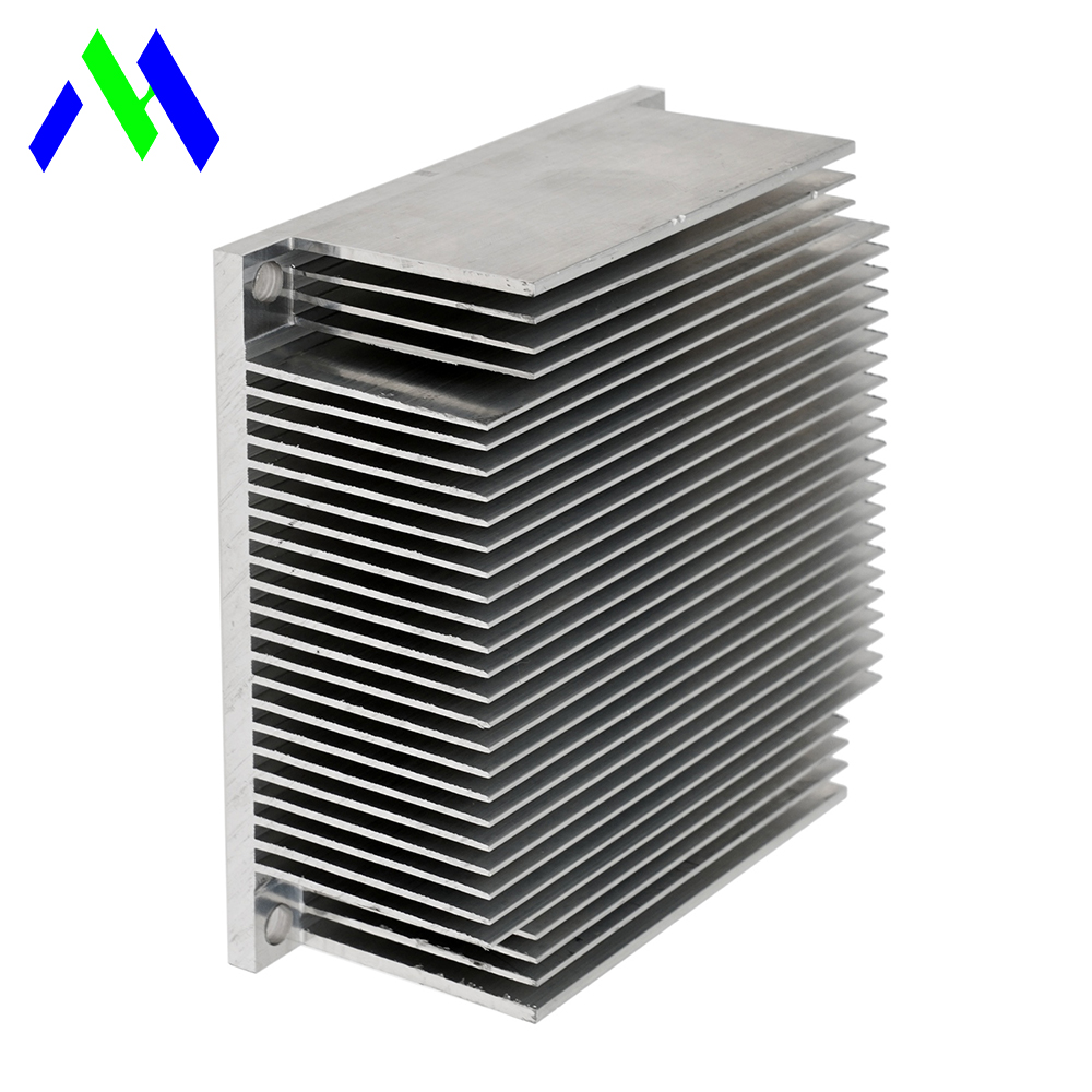
The extrusion process involves forcing heated aluminum billets through a custom steel die to create continuous profiles. This method produces long lengths of material with a consistent cross-section, which are subsequently cut to the desired length. The process is highly efficient for generating straight-fin geometries commonly used in standard cooling applications. The extrusion press applies thousands of tons of force, pushing the plasticized aluminum through the die openings. The profile is then cooled, stretched to relieve internal stresses, and cut.
Manufacturers typically utilize 6000 series aluminum alloys, such as 6061 or 6063. These alloys provide an optimal balance of extrudability, structural strength, and a baseline thermal conductivity ranging from 160 to 200 W/m·K. While not as thermally conductive as pure aluminum, the 6000 series offers sufficient performance for a vast array of commercial and industrial applications. The addition of magnesium and silicon in these alloys allows for heat treatment (like T5 or T6 tempering), significantly improving the mechanical properties of the final part.
Die design is a specialized engineering discipline. The die must balance metal flow to ensure the base and fins extrude at the same rate. If the fins are too thin relative to the base, the metal will flow faster through the base portion, causing the profile to warp or tear as it exits the die. This flow dynamic dictates the minimum fin thickness and maximum aspect ratios achievable.
An aluminum extruded heat sink excels in linear, unidirectional airflow applications. They are ubiquitous in server racks, standard PC components, and industrial drives where fans channel air directly through parallel fins. The straight channels minimize pressure drop, allowing forced air to efficiently sweep heat away from the base. When you have a dedicated fan blowing across the fins, the continuous channels act like wind tunnels, maximizing the convective heat transfer coefficient.
The economic advantages of extrusion are significant. Low die tooling costs and rapid prototyping capabilities make it an attractive option for custom designs. Furthermore, the process supports highly scalable mass production. Extruded profiles also accommodate easy secondary machining, including cutting to length, CNC milling, drilling, and tapping for mounting hardware. You can order a long extrusion and cut it into 10mm slices for small components or 500mm lengths for large power inverters.
Surface finishing options for extrusions are extensive. Anodizing is the most common, providing electrical isolation, corrosion resistance, and improved thermal emissivity. Black anodizing can increase radiative heat transfer in passive applications. Chromate conversion coatings (like Alodine) offer corrosion protection while maintaining electrical conductivity for grounding purposes.
Extrusion imposes specific constraints on fin aspect ratios, typically capping at 10:1 or 15:1 depending on the alloy and die design. Pushing beyond these limits increases the risk of die breakage or fin deformation during the manufacturing process. Consequently, extruded fins are generally thicker (minimum ~1.0mm) compared to skived heat sinks, which limits the overall surface area density achievable within a given volume. If you need extremely dense fins, extrusion will not meet your requirements.
The fundamental 2D limitation restricts extruded profiles to continuous cross-sections. Creating cross-cut fins or complex multi-directional geometries requires expensive secondary CNC operations, negating the initial cost benefits. You cannot extrude a pin fin; you can only extrude a straight fin and then cross-cut it with a gang saw, which adds machining time and wastes material.
Extrusion requires a minimum base thickness to ensure material flows evenly through the die and prevents structural failure during fabrication. A very thin base with tall fins is nearly impossible to extrude reliably. This limits the ability to reduce weight in applications where base spreading resistance is less critical than overall mass.
The cold forged heat sink process utilizes high compressive forces to shape raw metal at room temperature. This high-pressure forming forces the metal into a precision mold cavity, creating near-net-shape components with complex 3D geometries in a single strike. The raw material, usually a slug of pure aluminum or copper, is placed in the die, and a punch descends, forcing the metal to flow upward into the fin cavities.
Cold forging offers exceptional material versatility. It commonly utilizes 1000 series pure aluminum (e.g., AL1050, AL1070), which boasts a thermal conductivity of ~220-230 W/m·K. The process also accommodates high-conductivity pure copper (C11000, ~400 W/m·K) or copper-aluminum hybrid solutions. The intense pressure eliminates internal air bubbles and creates a tighter, denser grain structure, significantly enhancing thermal transfer from the base to the fins. Unlike casting, there is no melting involved, so the material retains its pure thermal properties without the need for flow-enhancing additives like silicon.
The tooling for cold forging is massive and complex. The dies must withstand extreme internal pressures without deflecting or cracking. This requires high-grade tool steels and precise machining. The punch and die alignment must be perfect to ensure uniform fin thickness and base flatness. The process is highly repeatable, yielding parts with excellent dimensional stability once the tooling is dialed in.
Cold forging is uniquely capable of manufacturing a round heat sink, perfectly suited for cylindrical enclosures like LED downlights, industrial sports lighting, and automotive applications. The process excels in natural convection environments where omnidirectional airflow is required to dissipate heat effectively without relying on fans. The radial fin patterns allow air to flow upward regardless of the fixture's orientation.
Engineers leverage cold forging to produce high-density pin fins with extreme aspect ratios (up to 35:1) without secondary machining. This maximizes surface area within a compact footprint. Furthermore, cold forged components deliver up to 80% higher thermal conductivity than die-cast components using silicon-heavy alloys like ADC12 (~96 W/m·K), making them vastly superior for high-power passive cooling. The ability to forge a splayed pin fin heat sink allows for even greater air mixing and boundary layer disruption.
Forging produces a single, continuous piece of metal. There is no thermal interface resistance between the base and the fins, unlike bonded or soldered fin assemblies. This continuous grain structure provides the lowest possible thermal resistance path from the heat source to the cooling surface.
The primary barrier to adopting cold forging is the high initial tooling and mold costs associated with the forging dies. These hardened steel molds must withstand immense pressure, making them expensive to design and fabricate. This upfront investment necessitates high production volumes to achieve a reasonable per-unit cost. Prototyping a forged design usually involves CNC machining a block of pure aluminum, which mimics the geometry but not the exact grain structure of the final forged part.
Cold forging also faces limitations regarding overall footprint size. Extremely large heat sinks require prohibitively massive forging presses, restricting the practical dimensions of forged components. A 300mm x 300mm heat sink would require a press capacity rarely found in standard manufacturing facilities. Therefore, forging is generally reserved for smaller, high-density cooling applications.
The 1000 series pure aluminum used in forging possesses lower tensile strength than 6000 series alloys. The fins are softer and more susceptible to bending during handling, shipping, or installation. Careful packaging and mounting considerations are required in high-vibration environments to prevent deformation. You cannot easily tap threads directly into pure aluminum; threaded inserts or through-hole mounting strategies are often necessary.
Skiving involves shaving fins directly from a solid metal block using a specialized cutting tool. This process allows for significantly thinner fins and tighter pitch than extrusion, maximizing surface area density. However, skiving incurs higher cycle times and produces structurally vulnerable fins that bend easily. Skiving is excellent for forced convection in extremely tight spaces, like 1U servers, but lacks the structural robustness of extruded profiles.
Die casting injects molten metal into a mold, allowing for complex shapes but resulting in high porosity and lower thermal conductivity due to the necessary silicon additives. In contrast, cold forging maintains a dense grain structure and utilizes pure aluminum or copper, resulting in vastly superior thermal efficiency. Die casting is preferred for complex structural enclosures that also act as heat sinks, while forging is strictly for high-performance thermal dissipation.
The thermal transfer efficiency of the extruded 6000 series (~160-200 W/m·K) falls short of the cold-forged 1000 series (~220-230 W/m·K) and pure copper options (~400 W/m·K). The tighter grain structure in a forged part reduces thermal resistance at the base-to-fin junction. While both methods produce a single, continuous piece, the structural density achieved through forging facilitates faster heat dissipation. In high-power density applications, that 30 W/m·K difference between 6063 and AL1050 translates to several degrees of junction temperature reduction.
Grain orientation also plays a role. In extrusion, the grains are elongated parallel to the extrusion direction. In forging, the grains are compressed and flow up into the fins, aligning the thermal transfer path directly away from the base. This alignment slightly improves the effective thermal conductivity in the Z-axis.
Standard extruded fins offer a lower surface area-to-volume ratio compared to forged pin fins. Advanced geometries maximize ambient air mixing. The angled pins break up thermal boundary layers far more effectively than parallel extruded fins, enhancing convective heat transfer in passive environments. A boundary layer of warm air clings to flat surfaces; pin fins constantly disrupt this layer, forcing cooler ambient air into contact with the metal.
When designing for forced convection, straight extruded fins are usually superior because they offer less flow resistance. Pin fins create turbulence, which increases heat transfer but also drastically increases pressure drop. If the fan cannot overcome this pressure drop, airflow stalls, and the heat sink overheats.
Extrusion dominates in ducted, forced-air environments where fans channel air linearly through straight fins. The continuous channels minimize flow resistance. Conversely, cold forging excels in passive environments where heated air must escape from multiple angles. Pin fin geometries prevent thermal pooling by allowing omnidirectional airflow, ensuring continuous heat dissipation without active cooling.
Evaluation Metric | Aluminum Extruded Heat Sink | Cold Forged Heat Sink |
|---|---|---|
Material Base | 6000 Series Aluminum | 1000 Series Al, Pure Copper |
Thermal Conductivity | ~160 - 200 W/m·K | ~220 - 400 W/m·K |
Fin Geometry | 2D Linear / Straight | 3D Pin, Splayed, Round |
Aspect Ratio Limits | 10:1 - 15:1 | Up to 35:1 |
Tooling Cost | Low | High |
Omnidirectional Airflow | Poor | Excellent |
Structural Rigidity | High | Moderate (Softer Alloy) |
Secondary Machining | Easy | Difficult (Gummy Material) |
A significant risk involves tooling lock-in with cold forging. High upfront mold costs make design iterations expensive. Mitigation requires thoroughly validating thermal models using computational fluid dynamics (CFD) and rapid prototyping before committing to forging dies. Ensure the design meets all thermal and spatial requirements prior to mass production. CNC machining a prototype from AL1050 billet provides a highly accurate thermal representation of the final forged part.
Another risk is base flatness. Both extrusion and forging can result in slight concavity or convexity at the mounting base. A non-flat base creates microscopic air gaps between the heat sink and the component, destroying thermal transfer. Always specify a base flatness tolerance (e.g., 0.05mm per 100mm) and require a secondary CNC fly-cutting operation on the base if the raw process cannot hold that tolerance.
Evaluate your airflow environment to determine if linear extrusion or omnidirectional forging is required for your specific enclosure.
Calculate the necessary thermal conductivity to select between 6000 series aluminum, 1000 series aluminum, or pure copper based on your maximum junction temperature.
Validate designs with CFD simulations and CNC machined prototypes before committing to expensive forging molds or extrusion dies.
Specify strict base flatness tolerances and require secondary machining operations to ensure optimal contact with the thermal interface material.
A: Cold forging allows for the creation of pin fins and splayed geometries that enable omnidirectional airflow. This prevents hot air from trapping between fins, making it highly effective for natural convection where air must escape from multiple angles.
A: Yes, if paired with forced convection to drive air through the straight fins. For passive cooling of high-power LEDs in compact spaces, cold forged round heat sinks are generally preferred due to higher thermal conductivity.
A: The 6000 series alloys provide the necessary structural strength and extrudability to flow through dies without tearing. The 1000 series is too soft for standard extrusion processes but ideal for cold forging.
A: Yes, forging requires hardened steel molds capable of withstanding immense pressure, making initial tooling significantly more expensive than the relatively simple steel dies used for aluminum extrusion.
A: You can CNC machine cross-cuts into an extruded profile to create rectangular pin fins, but this adds significant machining time and material waste. True cylindrical or splayed pin fins are best achieved through cold forging.
A: A thicker base improves heat spreading from a small heat source across the entire width of the heat sink. However, excessive base thickness adds unnecessary weight and increases the thermal path length to the fins.